element14 Community
element14 Community
    Register Log In
  • Site
  • Search
  • Log In Register
  • Community Hub
    Community Hub
    • What's New on element14
    • Feedback and Support
    • Benefits of Membership
    • Personal Blogs
    • Members Area
    • Achievement Levels
  • Learn
    Learn
    • Ask an Expert
    • eBooks
    • element14 presents
    • Learning Center
    • Tech Spotlight
    • STEM Academy
    • Webinars, Training and Events
    • Learning Groups
  • Technologies
    Technologies
    • 3D Printing
    • FPGA
    • Industrial Automation
    • Internet of Things
    • Power & Energy
    • Sensors
    • Technology Groups
  • Challenges & Projects
    Challenges & Projects
    • Design Challenges
    • element14 presents Projects
    • Project14
    • Arduino Projects
    • Raspberry Pi Projects
    • Project Groups
  • Products
    Products
    • Arduino
    • Avnet Boards Community
    • Dev Tools
    • Manufacturers
    • Multicomp Pro
    • Product Groups
    • Raspberry Pi
    • RoadTests & Reviews
  • About Us
  • Store
    Store
    • Visit Your Store
    • Choose another store...
      • Europe
      •  Austria (German)
      •  Belgium (Dutch, French)
      •  Bulgaria (Bulgarian)
      •  Czech Republic (Czech)
      •  Denmark (Danish)
      •  Estonia (Estonian)
      •  Finland (Finnish)
      •  France (French)
      •  Germany (German)
      •  Hungary (Hungarian)
      •  Ireland
      •  Israel
      •  Italy (Italian)
      •  Latvia (Latvian)
      •  
      •  Lithuania (Lithuanian)
      •  Netherlands (Dutch)
      •  Norway (Norwegian)
      •  Poland (Polish)
      •  Portugal (Portuguese)
      •  Romania (Romanian)
      •  Russia (Russian)
      •  Slovakia (Slovak)
      •  Slovenia (Slovenian)
      •  Spain (Spanish)
      •  Sweden (Swedish)
      •  Switzerland(German, French)
      •  Turkey (Turkish)
      •  United Kingdom
      • Asia Pacific
      •  Australia
      •  China
      •  Hong Kong
      •  India
      •  Korea (Korean)
      •  Malaysia
      •  New Zealand
      •  Philippines
      •  Singapore
      •  Taiwan
      •  Thailand (Thai)
      • Americas
      •  Brazil (Portuguese)
      •  Canada
      •  Mexico (Spanish)
      •  United States
      Can't find the country/region you're looking for? Visit our export site or find a local distributor.
  • Translate
  • Profile
  • Settings
element14's The Ben Heck Show
  • Challenges & Projects
  • element14 presents
  • element14's The Ben Heck Show
  • More
  • Cancel
element14's The Ben Heck Show
Forum Need help identifying an early 90s PCB thru-hole transformer and a few other questions
  • Blog
  • Forum
  • Documents
  • Polls
  • Files
  • Members
  • Mentions
  • Sub-Groups
  • Tags
  • More
  • Cancel
  • New
Join element14's The Ben Heck Show to participate - click to join for free!
Actions
  • Share
  • More
  • Cancel
Forum Thread Details
  • State Suggested Answer
  • Replies 20 replies
  • Answers 7 answers
  • Subscribers 32 subscribers
  • Views 3153 views
  • Users 0 members are here
Related

Need help identifying an early 90s PCB thru-hole transformer and a few other questions

chrisbc
chrisbc over 7 years ago

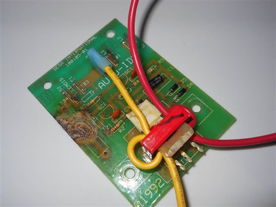
Hi. I need help identifying an early 90s PCB transformer. It's on an auto-idle control board from an early 90s gas-powered generator from a company that has since gone out of business. I'm not familiar with components but think I can identify all of the other components to remake another board in case of a catastrophic failure. The problem I'm having is identifying the size and type of what I think is a transformer. I've included a few pictures. It's located at the bottom of the board and has a yellow and red wire wrapped around it. The red wire comes from the generator head and goes out to a breaker to power the receptacles, and the yellow wire comes from a terminal lug next to another terminal lug which accepts the other (yellow) wire coming from the generator head.imageimageimage

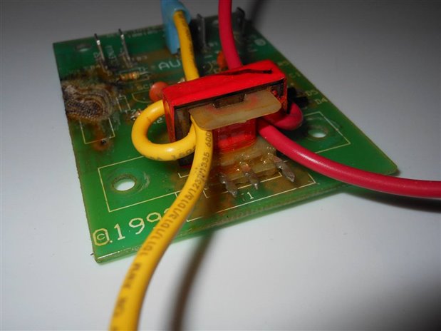
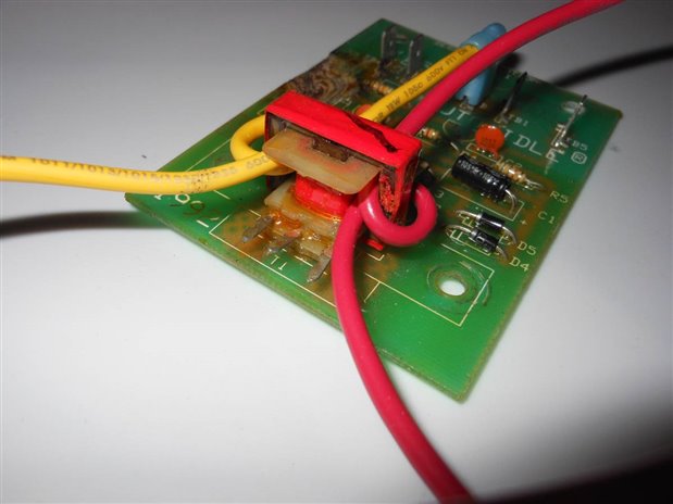
And can anyone tell how big the small capacitor is that's located to the right above the transformer? I can't find any marks on it other than the temperature rating.


I also have to replace a 5W 82ohm resistor that blew due to a bad Schottky diode that I've found and will replace. Would it be safer to replace the blown resistor with a 12W 82ohm resistor? And can I use an aluminum encased surface mount resistor on a thru-hole PCB?


Any help would be appreciated!

Attachments:
image
image
image
  • Sign in to reply
  • Cancel

Top Replies

  • jw0752
    jw0752 over 7 years ago +4 suggested
    Hi Chris, The small capacitor is probably marked on the side that is glued down. You may have to pry it loose carefully. You can up the wattage of a resistor without any consequence except that of a larger…
  • jw0752
    jw0752 over 7 years ago in reply to chrisbc +4 suggested
    Hi Chris, If you mount a power resistor on the board make sure it is in a raised position so air is free to flow around it. This will keep it from damaging the board. You may not get the full wattage dissipation…
  • three-phase
    three-phase over 7 years ago +3 suggested
    I would agree with jw0752 that the small transformer is a current transformer measuring the load on the sockets to allow the engine speed to be controlled based upon the load the generator is supplying…
Parents
  • jw0752
    0 jw0752 over 7 years ago

    Hi Chris,

    The small capacitor is probably marked on the side that is glued down. You may have to pry it loose carefully. You can up the wattage of a resistor without any consequence except that of a larger foot print. The transformer is being used to measure the current that is being delivered. As the current goes up so too the load on the motor and therefore the need to increase the throttle to maintain proper RPM. I would reuse the transformer if possible as they are quite hardy and not likely damaged.

    John

    • Cancel
    • Vote Up +4 Vote Down
    • Sign in to reply
    • Verify Answer
    • Reject Answer
    • Cancel
  • chrisbc
    0 chrisbc over 7 years ago in reply to jw0752

    Thanks John, I appreciate the help. Can I use an aluminum encased surface mount resistor on a thru-hole board? It has the same leads.


    And just in case of a fire or some other catastrophe, what size and/or type of transformer is it, and do they still make those types of transformers?

    • Cancel
    • Vote Up +1 Vote Down
    • Sign in to reply
    • Verify Answer
    • Cancel
  • jw0752
    0 jw0752 over 7 years ago in reply to chrisbc

    Hi Chris,

    If you mount a power resistor on the board make sure it is in a raised position so air is free to flow around it. This will keep it from damaging the board. You may not get the full wattage dissipation from an aluminum encased unless it is mounted to a heat sink but if you are going from a 5 watt to a 25 watt I am sure it will be capable of handling 5 watts. The transformer was probably OEM and manufactured for this application and not available except from the manufacturer of the generator. It does not look like a stock transformer and would be difficult to duplicate without the design specifications of the circuit.

    John

    • Cancel
    • Vote Up +4 Vote Down
    • Sign in to reply
    • Verify Answer
    • Reject Answer
    • Cancel
  • chrisbc
    0 chrisbc over 7 years ago in reply to jw0752

    Thanks again John. That was very helpful information and much appreciated. Take care


    Chris

    • Cancel
    • Vote Up +1 Vote Down
    • Sign in to reply
    • Verify Answer
    • Cancel
  • chrisbc
    0 chrisbc over 7 years ago in reply to jw0752

    John, I have one more question.. I think. I'm going to replace the 2 ceramic disc capacitors on the board to be safe. They both say 103Z on them which I've found are .01 uF. But I don't know what voltage rating I would need. Do you know what voltage I would need? The ceramic disc capacitors I'll be replacing measure about 6mm across. Does that give any indication as to the voltage rating I would need?

    • Cancel
    • Vote Up 0 Vote Down
    • Sign in to reply
    • Verify Answer
    • Cancel
  • jw0752
    0 jw0752 over 7 years ago in reply to chrisbc

    Hi Chris,

    You are correct it is a .01 uF and the Z indicates a 20% tolerance. From your picture it appears that there is a line drawn under the 103Z and this would indicate 50 / 100 volts according to the literature. If there is no line then it is suppose to be 500 V. No one seems to be too concerned with the voltage on ceramic disks and it is extremely rare for them to degrade or fail. As far as the size being an indicator of the voltage I would go with thickness as a better indicator of higher voltage.

    John

    • Cancel
    • Vote Up +1 Vote Down
    • Sign in to reply
    • Verify Answer
    • Reject Answer
    • Cancel
  • chrisbc
    0 chrisbc over 7 years ago in reply to jw0752

    Great! Thanks once again for all of your help John. You've been extremely helpful and I very much appreciate it. Thanks!


    Chris

    • Cancel
    • Vote Up 0 Vote Down
    • Sign in to reply
    • Verify Answer
    • Cancel
Reply
  • chrisbc
    0 chrisbc over 7 years ago in reply to jw0752

    Great! Thanks once again for all of your help John. You've been extremely helpful and I very much appreciate it. Thanks!


    Chris

    • Cancel
    • Vote Up 0 Vote Down
    • Sign in to reply
    • Verify Answer
    • Cancel
Children
No Data
element14 Community

element14 is the first online community specifically for engineers. Connect with your peers and get expert answers to your questions.

  • Members
  • Learn
  • Technologies
  • Challenges & Projects
  • Products
  • Store
  • About Us
  • Feedback & Support
  • FAQs
  • Terms of Use
  • Privacy Policy
  • Legal and Copyright Notices
  • Sitemap
  • Cookies

An Avnet Company © 2025 Premier Farnell Limited. All Rights Reserved.

Premier Farnell Ltd, registered in England and Wales (no 00876412), registered office: Farnell House, Forge Lane, Leeds LS12 2NE.

ICP 备案号 10220084.

Follow element14

  • X
  • Facebook
  • linkedin
  • YouTube