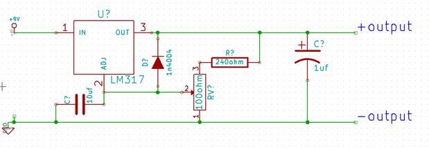
I'm building a laser driver for a dvd laser burner. I needs 200-250 mA and 1.8-2.2V.
Is it the right setup? Is the trimpot setup correct? The multimetre shows6.43V and the trimpot doesn't seem to change anything.
I'm building a laser driver for a dvd laser burner. I needs 200-250 mA and 1.8-2.2V.
Is it the right setup? Is the trimpot setup correct? The multimetre shows6.43V and the trimpot doesn't seem to change anything.