element14 Community
element14 Community
    Register Log In
  • Site
  • Search
  • Log In Register
  • Community Hub
    Community Hub
    • What's New on element14
    • Feedback and Support
    • Benefits of Membership
    • Personal Blogs
    • Members Area
    • Achievement Levels
  • Learn
    Learn
    • Ask an Expert
    • eBooks
    • element14 presents
    • Learning Center
    • Tech Spotlight
    • STEM Academy
    • Webinars, Training and Events
    • Learning Groups
  • Technologies
    Technologies
    • 3D Printing
    • FPGA
    • Industrial Automation
    • Internet of Things
    • Power & Energy
    • Sensors
    • Technology Groups
  • Challenges & Projects
    Challenges & Projects
    • Design Challenges
    • element14 presents Projects
    • Project14
    • Arduino Projects
    • Raspberry Pi Projects
    • Project Groups
  • Products
    Products
    • Arduino
    • Avnet & Tria Boards Community
    • Dev Tools
    • Manufacturers
    • Multicomp Pro
    • Product Groups
    • Raspberry Pi
    • RoadTests & Reviews
  • About Us
  • Store
    Store
    • Visit Your Store
    • Choose another store...
      • Europe
      •  Austria (German)
      •  Belgium (Dutch, French)
      •  Bulgaria (Bulgarian)
      •  Czech Republic (Czech)
      •  Denmark (Danish)
      •  Estonia (Estonian)
      •  Finland (Finnish)
      •  France (French)
      •  Germany (German)
      •  Hungary (Hungarian)
      •  Ireland
      •  Israel
      •  Italy (Italian)
      •  Latvia (Latvian)
      •  
      •  Lithuania (Lithuanian)
      •  Netherlands (Dutch)
      •  Norway (Norwegian)
      •  Poland (Polish)
      •  Portugal (Portuguese)
      •  Romania (Romanian)
      •  Russia (Russian)
      •  Slovakia (Slovak)
      •  Slovenia (Slovenian)
      •  Spain (Spanish)
      •  Sweden (Swedish)
      •  Switzerland(German, French)
      •  Turkey (Turkish)
      •  United Kingdom
      • Asia Pacific
      •  Australia
      •  China
      •  Hong Kong
      •  India
      • Japan
      •  Korea (Korean)
      •  Malaysia
      •  New Zealand
      •  Philippines
      •  Singapore
      •  Taiwan
      •  Thailand (Thai)
      • Vietnam
      • Americas
      •  Brazil (Portuguese)
      •  Canada
      •  Mexico (Spanish)
      •  United States
      Can't find the country/region you're looking for? Visit our export site or find a local distributor.
  • Translate
  • Profile
  • Settings
Project Videos
  • Challenges & Projects
  • element14 presents
  • Project Videos
  • More
  • Cancel
Project Videos
Documents How Far Can I2C Go? -- Episode 666
  • Documents
  • Members
  • Mentions
  • Sub-Groups
  • Tags
  • More
  • Cancel
  • New
Join Project Videos to participate - click to join for free!
Related
Recommended
Engagement
  • Author Author: cstanton
  • Date Created: 23 May 2025 9:30 AM Date Created
  • Last Updated Last Updated: 23 May 2025 11:10 AM
  • Views 3474 views
  • Likes 8 likes
  • Comments 23 comments

How Far Can I2C Go? -- Episode 666

Have you ever wondered if the humble I2C protocol, designed for short-distance communication on a PCB, could work over a stretched-out distance? Clem, an innovative DIY enthusiast, dives headfirst into this question in his latest experiment. Armed with two Raspberry Pi Pico microcontrollers, a coiled-up RG58 coaxial cable, and a few unconventional ideas, he sets out to see if I2C can bridge the gap between devices separated by meters—even outdoors.

Watch the Episode

You don't have permission to edit metadata of this video.
Edit media
x
image
Upload Preview
image

The Problem: Taking I2C Beyond the PCB

I2C (Inter-Integrated Circuit) is a reliable protocol, but it’s typically intended for communication between components within a single PCB or, at best, over very short distances. The main challenge? Capacitance—as wires get longer, their ability to maintain signal integrity decreases. Clem had an ambitious thought: What if he could use I2C as a bus system running throughout his workshop to connect micro-controllers and sensors scattered across different areas? Could it work over 10 or even 20 meters of cable? Only one way to find out—test it.

image

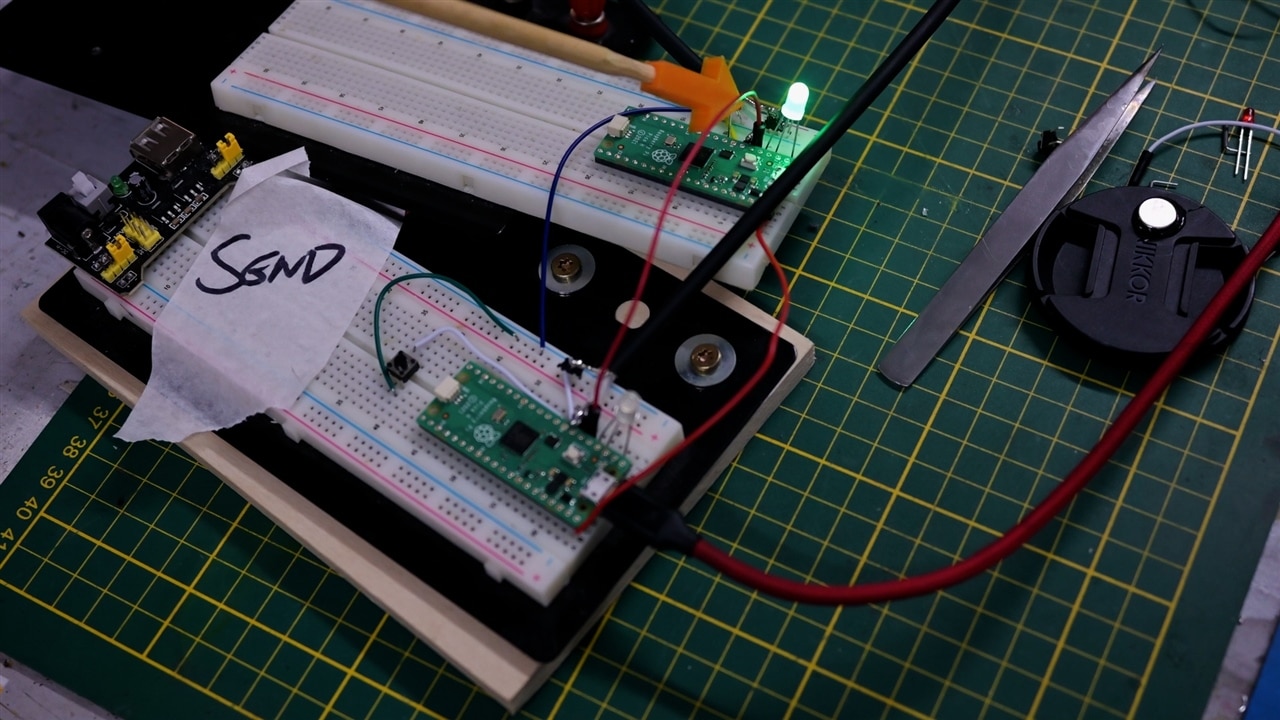
The Setup: Breadboards, Raspberry Pi Picos, and Coaxial Cable

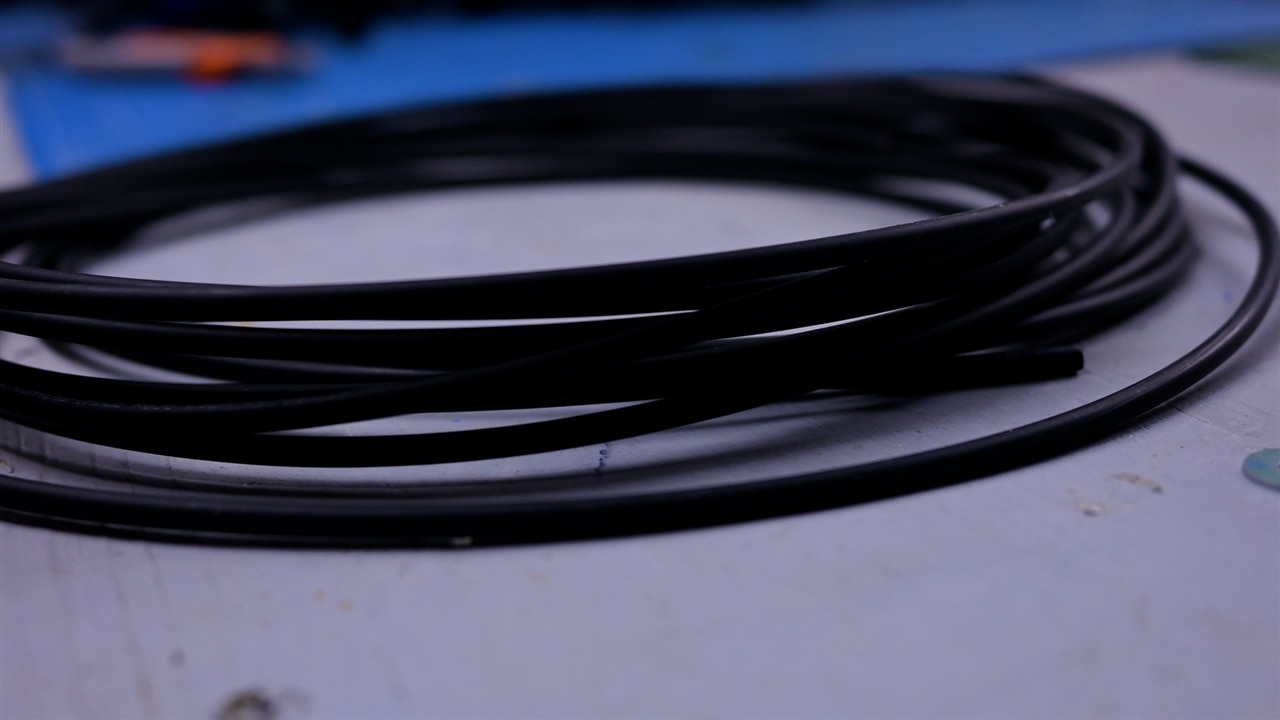
Clem began his experiment with a simple setup on breadboards. Using two Raspberry Pi Pico micro-controllers, he established a basic I2C connection with standard jumper wires to simulate a local, short-distance connection. With the baseline working, it was time to introduce the star of the experiment: a 10-meter-long RG58 coaxial cable. Why coaxial? Its shielding properties make it a good candidate for reducing interference, a critical factor when extending the range of I2C.

He connected the two micro-controllers through the coiled cable and ran initial tests. The results were promising—communication was intact! But Clem wasn’t done yet. He wanted to push the boundaries even further.

image

Taking It Outside: Testing I2C Over 20 Meters

With the system working over 10 meters of cable, Clem decided to push his experiment to the extreme. He ran the coaxial cable through a cellar window and out into his garden, effectively extending the distance to 20 meters. The sight of an I2C bus stretching through a garden might have seemed bizarre, but it was all in the name of science!

To his delight, the I2C communication still worked. By using the RG58 cable's shielding to his advantage, Clem demonstrated that the protocol could handle significant distances, far beyond its typical use case.

image

Bill of Materials

Product Name Manufacturer Quantity Buy Kit
Raspberry Pi pico H Raspberry Pi 2 Buy Now
RG58 50Ohm Coaxial Cable Multicomp Pro 20 Buy Now

Supporting Code and Links

  •  Supporting Files for Episode 666 of element14 presents  

element14 presents

element14 presents  |  About Clem  |  Project Videos

  • i2c bus length limit
  • i2c over coaxial cable
  • rg58 i2c testing
  • i2c wiring tips
  • extend i2c range
  • microcontroller i2c setup
  • i2c protocol tutorial
  • long range i2c experiment
  • raspberry pi pico i2c
  • i2c with raspberry pi
  • i2c communication distance
  • i2c on breadboard
  • i2c signal integrity
  • i2c workshop project
  • friday_release
  • i2c long distance
  • Share
  • History
  • More
  • Cancel
Actions
  • Share
  • More
  • Cancel
  • Sign in to reply

Top Comments

  • mayermakes
    mayermakes 7 months ago in reply to kmikemoo +1
    you erased the erase out of the board.
Parents
  • jc2048
    jc2048 7 months ago

    Why 50R cable? If you use typical 75R coax the capacitance per metre would be lower, usually something like 60-70pF/m (go for stranded core if you're going to be flexing the cable a lot - quite a lot of video coax is solid core for fixed installations). Some of the old networking standards that ran on coax used even higher characteristic impedances, with even lower distributed capacitance values (RG62, 93R, 45pF/m, for instance), so if you could find some old lengths, that might work even better.

    If you're worried about the resistance per metre - I'm not sure why you need to be? - a larger overall diameter coax will probably have a larger diameter core (to maintain the geometry), so will tend to have lower DC resistance along the core.

    The shield has very good current carrying capability (seriously good - in my old Tek portable oscilloscope, they degauss the steel shield that magnetically shields the tube, at start-up, by passing a high current through the shield of the coax that forms the delay line and is wrapped around the tube shield: it goes "thump!" every time you turn it on, which is a bit worrying until you understand the reason for it). There's no reason I can see why you couldn't use the two shields for carrying your power, if you wanted to, though there's the very obvious danger of shorting them. I don't think having an essentially DC potential on the shield affects the screening properties (decouple well at both ends to ensure that, but you'd do that anyway).

    Personally, I'd try it with Cat5 cable as well (about 50pF/m) as an experiment - look at the signals at the far end to see if there's much crosstalk beween the clock and the data. With cat5 cable, you could use the spare pairs for power.

    Which leads us to: why aren't you looking at the signals with an oscilloscope? That should quickly show you why it succeeds at 10m and fails at 20m.

    BTW if you want to find out how robust it is, throw pseudorandom data continuously across the link for 24 hours and see how many errors you get - pressing a button a couple of times isn't much of a test.

    • Cancel
    • Vote Up 0 Vote Down
    • Sign in to reply
    • More
    • Cancel
  • mayermakes
    mayermakes 7 months ago in reply to jc2048

    thanks for the extensive comment.
    So the 50 ohm choice stems from the intended use of I2c on circuit boards and 50Ohms is the standard for impedance controlled traces, so I gave that the best chance of matching with common pullup values etc.. running the power over one of the shields did not work reliably for me(brownout), a big cap on each end might have helped.
    Ethernet cable was not reliable for more than a few meters, I suspect the isolation of SDA and SCL to each other made the coax the better choice.
    I found my sweet spot at 10 meters 50Ohm coax, with internal pullups and independent PSU.

    And on the general why this not that etc. I have very limited time for each video  including sourcing and post production which boils down to usually only one shot to get it done , So i just try until I succeed and wrap it up. Its my intention to get people thinking and trying it themselves and possibly finding better solutions . So I think my goal was achieved by getting you to think hard about the topic and coming up with possible better variants.
    So thanks again for chiming in!

    • Cancel
    • Vote Up 0 Vote Down
    • Sign in to reply
    • More
    • Cancel
Comment
  • mayermakes
    mayermakes 7 months ago in reply to jc2048

    thanks for the extensive comment.
    So the 50 ohm choice stems from the intended use of I2c on circuit boards and 50Ohms is the standard for impedance controlled traces, so I gave that the best chance of matching with common pullup values etc.. running the power over one of the shields did not work reliably for me(brownout), a big cap on each end might have helped.
    Ethernet cable was not reliable for more than a few meters, I suspect the isolation of SDA and SCL to each other made the coax the better choice.
    I found my sweet spot at 10 meters 50Ohm coax, with internal pullups and independent PSU.

    And on the general why this not that etc. I have very limited time for each video  including sourcing and post production which boils down to usually only one shot to get it done , So i just try until I succeed and wrap it up. Its my intention to get people thinking and trying it themselves and possibly finding better solutions . So I think my goal was achieved by getting you to think hard about the topic and coming up with possible better variants.
    So thanks again for chiming in!

    • Cancel
    • Vote Up 0 Vote Down
    • Sign in to reply
    • More
    • Cancel
Children
  • jc2048
    jc2048 7 months ago in reply to mayermakes

    Fair enough. I'll stop giving you tasks to do.

    And 'well done' on even doing the video, I couldn't manage that in a month of sundays.

    My thinking above is all a bit muddled. I was thinking that 100kHz is slow, so the line will look like a lumped capacitor and you needed to minimise the capacitance, but of course the edges are faster and will see 10m as a transmission line, particularly the driven falling edge.

    It's messy, because the I2C standard was never intended for this. Philips originally designed it to meander around a circuit board, inside a consumer device like a television, often on a 2-layer board.

    Given what you've just said, I think you might be getting it to work not by matching into the cable, but by not matching, so that the end of the cable looks capacitive and slows the edge enough that the reflection that comes back doesn't cause too much disruption. That might explain why more capacitance per metre seems to be giving you a better result. If that is the case, then trying a few hundred pF of capacitance loading the driving end might enable the network cable to work out to the 10m you're getting for the coax.

    Another approach might be to accept that the fast falling edge sees the line as a transmission line and use AC termination, so that the termination just exists whilst the signal is changing, but doesn't permanently load things and mess up the signalling levels. For the network cable a 100R resistor in series with however many tens of pF is needed to give a time constant that covers the edge period might do it.

    Anyway, a couple of ideas there that anyone reading might experiment with.

    But if you're serious about a really cheap, small-scale network, I'd suggest looking at an RS422/RS485 transceiver hanging on a UART port, and sending on a single pair. Writing some simple packet stuff to send and receive under the control of a single master isn't too difficult.

    • Cancel
    • Vote Up 0 Vote Down
    • Sign in to reply
    • More
    • Cancel
  • Jan Cumps
    Jan Cumps 7 months ago in reply to mayermakes

    >  I have very limited time for each video  including sourcing and post production which boils down to usually only one shot to get it done 

    That seems the faith of every contracted technology video blogger on youtube.

    • Cancel
    • Vote Up 0 Vote Down
    • Sign in to reply
    • More
    • Cancel
  • mayermakes
    mayermakes 7 months ago in reply to Jan Cumps

    time constraints are part of the game and for me they are a good thing otherwise I would get stuck and procrastinate /never really finish a thing. with the deadline looming I need to find a solution within boundaries. So as long as I can set the limits myself(because I know how long things take me and what hickups to expect, it works great but of course limits project scope.

    I learned the hard way to never again let someone set any boundary for any project who is not able to pull it off on their own. If somenone does not have the needed skills / experience they should not make any such Decisions but listen to the ones that do have the skills and let them evaluate.

    On this one I set my usual timeframe and it was always out of scope to create a revolutionary bus system, the scope was just to answer asimple questiion with practical application, which it did and got you people to think about it and maybe try your own improved records!

    • Cancel
    • Vote Up 0 Vote Down
    • Sign in to reply
    • More
    • Cancel
element14 Community

element14 is the first online community specifically for engineers. Connect with your peers and get expert answers to your questions.

  • Members
  • Learn
  • Technologies
  • Challenges & Projects
  • Products
  • Store
  • About Us
  • Feedback & Support
  • FAQs
  • Terms of Use
  • Privacy Policy
  • Legal and Copyright Notices
  • Sitemap
  • Cookies

An Avnet Company © 2026 Premier Farnell Limited. All Rights Reserved.

Premier Farnell Ltd, registered in England and Wales (no 00876412), registered office: Farnell House, Forge Lane, Leeds LS12 2NE.

ICP 备案号 10220084.

Follow element14

  • X
  • Facebook
  • linkedin
  • YouTube