


Mark builds a mint tin emergency radio using an Arduino Nano, a TEA5767 FM receiver module, a custom PCB, and a coin cell–powered microcontroller-controlled supply. The challenge was designing a compact circuit that fits into a metal mint tin while avoiding shorts, using the housing itself as an antenna, and creating a power latch system for reliable operation. The radio is programmed to lock onto a single predefined station for emergency use, with careful soldering and component placement to make the design practical and portable.
Watch the Episode
Mark set out to build a compact FM radio that fits inside a mint tin, designed specifically for emergencies. Instead of tuning across stations in a crisis, this radio is programmed to receive just one predefined frequency. With that focus, Mark wanted a reliable, portable device that can be switched on quickly when it’s needed most.
In his own words:
"Imagine you are in crisis. Maybe your town got flooded or there is a forest fire coming your way. Maybe even worse… But I hope not! Anyway, during crisis people are under a lot of stress. Wait! I’ll have to switch on the radio to listen if there are any emergency broadcasts to give us more information about the current crisis. What station was it? I don’t remember…. Help us.
Wouldn’t it save a lot of stress if you had a ready to go radio that is already tuned into the local emergency station whenever it’s switch on?" - Mark
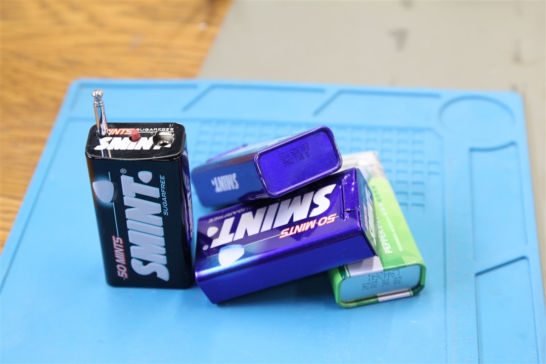
"So in this project I’m building a small Arduino based radio that automatically tunes to a local station that you pre-defined in the Arduino code. I will be using a radio module that has all the components I need to build an FM receiver. All I need to add are some connectors and a small Arduino. Yeah,, batteries are also a necessity. An antennae can be useful but you can do without by using a tin can housing ( a mint box) that serves as antenna." - Mark
Hardware Used
For this build, Mark used a mix of common and easily available components:
-
Arduino Nano – the microcontroller at the core of the project.
-
TEA5767 FM Receiver Module – the main radio chip.
-
Custom PCB – designed by Mark to keep the layout compact.
-
Coin Cell Batteries with Clips – providing power for portability.
-
Push Button – used to control the power latch system.
-
3.5mm Audio Jack – for connecting headphones.
-
Metal Mint Tin – serving as the enclosure and optionally as part of the antenna.
-
Capacitor (C1) – linking the antenna signal to the headset ground.
Circuit Design
Mark’s schematic covered three important areas:
-
Radio Section – built around the TEA5767, supported with small passive components on the PCB.
-
Power Section – a microcontroller-controlled latch circuit that let the push button start up the system, keep it powered, and safely shut it down.
-
Antenna Options – either connecting the mint tin housing to the circuit via C1 or attaching a dedicated wire. Care was needed to ensure the housing didn’t short against other PCB traces.
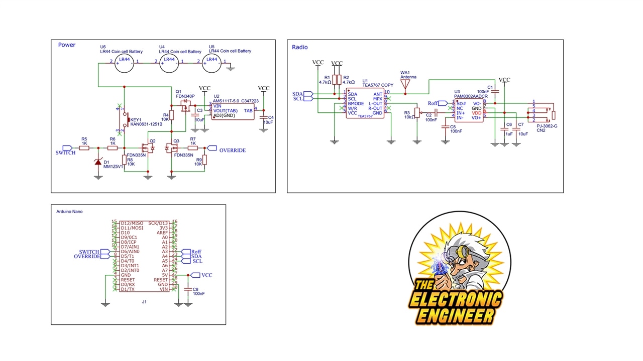
"So the schematic can be divided into 3 blocks. The power block is optional as you can choose to use feed the circuit by using the usb port on the Arduino. However, to build a standalone radio that fits in a mintbox, you will need to build the power section as well. The block with the Arduino is self-explanatory and the radio block is not hard if you follow the connections.
The whole circuit is powered by 3 coin cell batteries. When the radio is off no fet’s are conducting. By pressing the pushbutton KEY1, Q2 will conduct and it will drive the gate of Q1to ground, causing Q1 to conduct. By conducting, Q1 will feed power to the regulator U2 and the Arduino will power up. You will need to press and hold the pushbutton for 2 seconds so that IO pin D5 on the Arduino can be activated to drive Q3. OVERRIDE Line). From that moment on, the pushbutton can be released and gets a new function. By monitoring D6 on the Arduino ( SWITCH Line), the Arduino can now detect the Pushbutton as input. The software is programmed to shut down the Arduino if this button is pressed and hold for a longer time. The Arduino shutting down will also shut down the power supply." - Mark
Assembly
Assembly was done carefully under a microscope. Mark’s approach was to tack down one pad of each surface mount part, then solder the rest for accurate placement. Once the SMD parts were installed, he moved on to the through-hole components: the audio connector, push button, and battery clips. The Arduino Nano was soldered directly, with only the required pins connected to save space.
Before installing into the case, Mark powered the PCB from a bench supply with current limiting enabled. This way, any shorts could be caught without damaging the board. Once the circuit passed testing, he mounted it inside the mint tin, adding insulation tape to prevent the board from contacting the metal case.
Programming
On the software side, Mark programmed the Arduino Nano using three libraries:
-
Wire – for I²C communication.
-
Radio – to drive the TEA5767.
-
EasyButton – to handle button inputs.
The code initialises the radio and locks it to a single station. The button is programmed so a short press-and-hold switches the radio on, while a longer press powers it down. During development, the radio frequency and button actions were verified via the serial monitor. Users can easily adjust the tuned frequency in the code before uploading.
"In the Arduino sketch, the radio frequency of the station you want to listen to is defined as fixed. (#define FIX_STATION 10530 // listen to 105.30 Mhz on FM))
If you are building this setup on a breadboard, make sure you include R1 and R2 as those are crucial for the I2C bus to function. If you hear no sound on the plugin headset, try adjust R3 to control the volume.
C1 has a special function as it couples the joined wire of your headset to the receiver circuit of the radio. This way the joined wire has another function: antenna. This is a neat trick that was used in the older Walkman radio’s ( for those who remember those). Pay attention, in the schematic C1 is defined as 100nf but that’s not correct. It should be in the pf range. It’s a bit trial and error but about 50 to 100pf will do the trick." - Mark
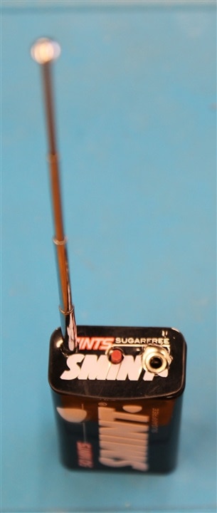
Finishing Touches
Mark created a template to drill precise holes in the mint tin for the audio jack, button, and antenna connector. The antenna can be a direct connection to the case or an external wire. Once everything was installed, the project looked neat and compact, resembling a discreet little radio gadget.
Mark’s mint tin radio shows how a practical emergency receiver can be built with an Arduino Nano, TEA5767 module, custom PCB, and coin cell batteries. The main challenges included avoiding shorts in a metal enclosure, designing a reliable power latch system, and making the housing itself serve as an antenna. The end result is a portable, single-station FM radio that’s simple to use in emergencies: switch it on and listen right away, no tuning required.
Supporting Files and Links
Bill of Materials
| Product Name | Manufacturer | Quantity | Buy Kit |
|---|---|---|---|
| MULTICOMP PRO Battery, 1.5 V, SR44, Silver Oxide, 162 mAh, Pressure Contact, 5 | MULTICOMP PRO | 3 | Buy Now |
| ARDUINO ARDUINO NANO, EVALUATION BOARD | ARDUINO | 1 | Buy Now |
| YAGEO SMD Multilayer Ceramic Capacitor, 0.1 µF, 50 V, 0805 [2012 Metric], ± 10%, X7R | YAGEO | 10.0 | Buy Now |
| SAMSUNG ELECTRO-MECHANICS SMD Multilayer Ceramic Capacitor, 10 µF, 25 V, 0805 [2012 Metric], ± 10%, X5R | SAMSUNG ELECTRO-MECHANICS | 5.0 | Buy Now |
| PANASONIC SMD Chip Resistor, 4.7 kohm, ± 0.5%, 100 mW, 0805 [2012 Metric], Thick Film, Precision | PANASONIC | 10.0 | Buy Now |
| VISHAY Trimmer, Single Turn, Cermet, Top Adjust, 10 kohm, Surface Mount, 1 Turns | VISHAY | 1.0 | Buy Now |
| SAMSUNG ELECTRO-MECHANICS SMD Multilayer Ceramic Capacitor, 1 µF, 50 V, 0805 [2012 Metric], ± 10%, X7R | SAMSUNG ELECTRO-MECHANICS | 5.0 | Buy Now |
| CLIFF ELECTRONIC COMPONENTS Phone Audio Connector, 5 Contacts, Jack, 3.5 mm, PCB Mount, Tin over Nickel Plated Contacts | CLIFF ELECTRONIC COMPONENTS | 5.0 | Buy Now |
| DIODES INC. Audio Power Amplifier, 2.5W x 1 @ 4Ohm, D, 1 Channels, 2V to 5.5V, SOIC, 8 Pins | DIODES INC. | 1.0 | Buy Now |
| SAMSUNG ELECTRO-MECHANICS SMD Multilayer Ceramic Capacitor, 10 µF, 50 V, 1206 [3216 Metric], ± 10%, X5R | SAMSUNG ELECTRO-MECHANICS | 5.0 | Buy Now |
| DIODES INC. Zener Single Diode, 5.1 V, 500 mW, SOD-123, 2 Pins, 150 °C, Surface Mount | DIODES INC. | 5.0 | Buy Now |
| ONSEMI Power MOSFET, P Channel, 20 V, 2 A, 0.06 ohm, SOT-23, Surface Mount | ONSEMI | 5.0 | Buy Now |
| ONSEMI Power MOSFET, N Channel, 20 V, 1.7 A, 0.07 ohm, SOT-23, Surface Mount | ONSEMI | 5.0 | Buy Now |
| NEOHM - TE CONNECTIVITY SMD Chip Resistor, 10 kohm, ± 5%, 125 mW, 0805 [2012 Metric], Thick Film, General Purpose | NEOHM - TE CONNECTIVITY | 10.0 | Buy Now |
| NEOHM - TE CONNECTIVITY SMD Chip Resistor, 1 kohm, ± 5%, 125 mW, 0805 [2012 Metric], Thick Film, General Purpose | NEOHM - TE CONNECTIVITY | 10.0 | Buy Now |
| TEXAS INSTRUMENTS Fixed LDO Voltage Regulator, 6.4V to 15V, 1.2V Dropout, 5Vout, 800mAout, SOT-223-3 | TEXAS INSTRUMENTS | 2.0 | Buy Now |
| TE CONNECTIVITY Tactile Switch, FSMRAJ, Side Actuated, Through Hole, 260 gf, 50mA at 24VDC | TE CONNECTIVITY | 10.0 | Buy Now |
| Additional Items | |||
| Antenna | |||
| Housing Mint Box | |||
| Radio Pcb | |||
| Battery Clips for coin cell CR/LR42 | |||


