

Mark takes you through the full build of a DIY pulse induction metal detector and explains the principles behind how it detects metal. He covers the electronics design, coil winding and shielding, and how an ESP32 is used to generate pulses, analyse the return signal, and provide audio and visual feedback. The project is designed to be adjustable and extensible, allowing you to tune detection behaviour and explore how different parameters affect performance. Mark also shares practical insights from building and testing the detector, making the video useful for anyone interested in metal detection or hands-on electronics.
Watch the Project
Building a metal detector is a good way to explore electromagnetics, analog signal processing, and embedded firmware in a single project. When Mark Donners started this build, he did not begin with a fixed design or a specific performance target. Instead, the goal was to understand how metal detectors work and to create a detector that could be adjusted, explored, and improved.
To build that foundation, Mark first studied the underlying theory. A key reference was Inside the Metal Detector by Carl Moreland, which explains the different detection methods used in commercial designs. From this research it became clear that, while there are several detector types, they all rely on coils and changes in electromagnetic behaviour. For this project, Mark chose a pulse induction approach because it is well suited to experimentation and relatively tolerant of environmental conditions.
What Is a Pulse Induction Metal Detector?
A pulse induction (PI) metal detector works by sending short, high-energy pulses through a coil and then observing what happens when the pulse stops. As Mark explains in the video:
“What we do is generate a pulse, send it to the coil, and then listen back on the same coil and follow the signal.”
Each pulse creates a magnetic field around the coil. When the pulse ends, the coil does not immediately return to rest. Instead, it produces a decaying oscillation, often referred to as ringing. The presence of metal near the coil changes how long this ringing lasts and how strong it is. By measuring those changes, the detector can determine when metal is present.
Some pulse detectors use a single coil for both transmitting and receiving, while others use separate coils. At the design stage, Mark did not yet know which configuration would work best for his setup, so the hardware was designed to support both options.
Overall System Design
The detector is built around an ESP32, which handles pulse generation, signal sampling, user input, display output, and audio feedback. Around that core, the system includes:
-
A custom analog front end for driving the coil and conditioning the received signal
-
A graphic display for visual feedback
-
An audio board with speaker or headphone output
-
Adjustable controls for tuning detection behaviour
-
Interchangeable coils
Early in the video, Mark summarises the concept simply:
“This one uses an ESP32 and a graphic display, and it has a nice sound for you to detect metal.”
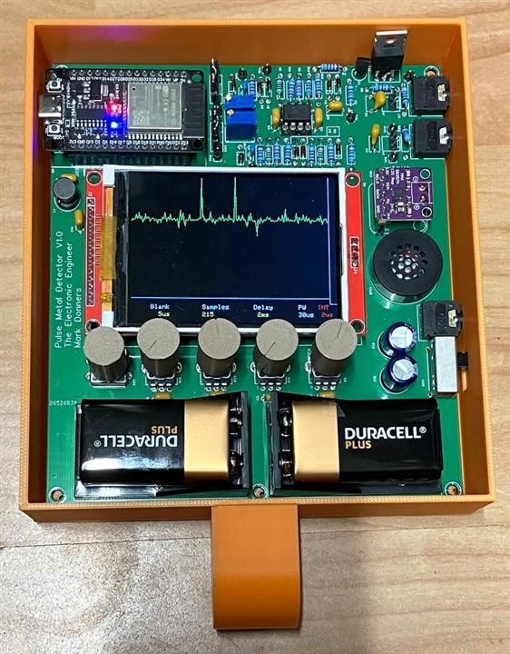
User Interface and Controls
The detector is designed to be adjusted while in use. The front panel includes four potentiometers, a touch button, and a power switch. These inputs allow the user to change detection parameters without modifying the firmware.
Using the controls, you can adjust:
-
Blanking time, which sets how long the system waits after a pulse before listening
-
The number of samples taken during each measurement
-
The delay between measurement sweeps
-
The sampling interval
Mark encourages users to actively adjust these settings while testing:
“You can just mess around with those parameters and see how that works out for you.”
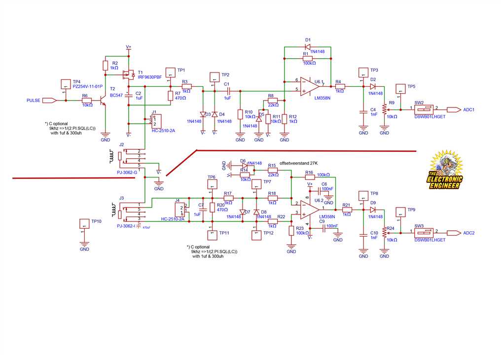
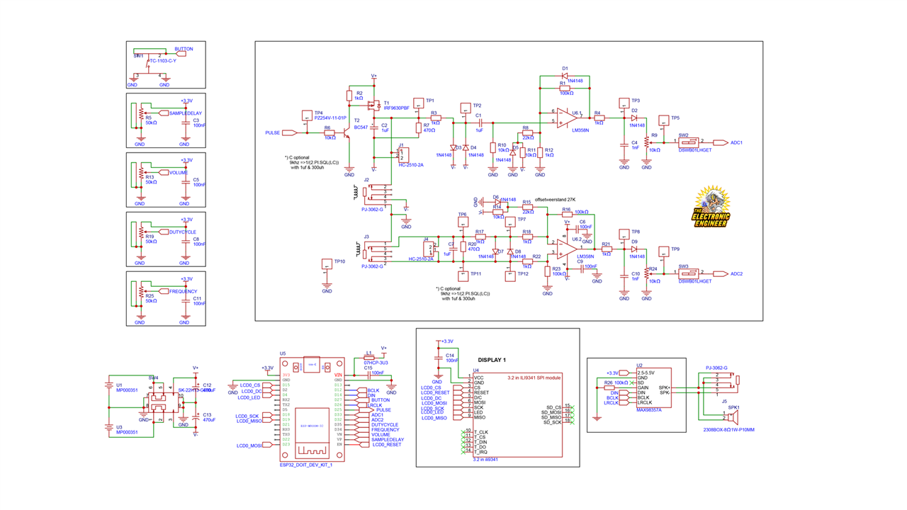
Analogue Front-End Circuitry
The analogue circuitry is divided into two nearly identical sections.
Transmit and Receive Channel
The upper section of the circuit drives the transmit coil. A short pulse generated by the ESP32 switches a MOSFET, boosting the signal to the full supply voltage, around 18 V peak. This produces a strong magnetic pulse in the coil.
Once the pulse ends, the coil begins to ring due to its inductance. This signal is carefully processed:
-
Diodes clip the high-energy pulse to protect the analogue circuitry
-
Only the low-level ringing signal is passed through
-
The signal is amplified, rectified, and filtered
-
The processed voltage is fed into the ESP32’s ADC
Receive-Only Channel
The lower section of the circuit uses the same signal conditioning chain but does not generate pulses. It continuously listens to a connected coil.
Mark explains why both circuits were included:
“At the time that I designed this, I had no idea yet if I’m going to use both the circuits or just one only. So I left both in there.”
This makes the design flexible for experimenting with different coil arrangements.
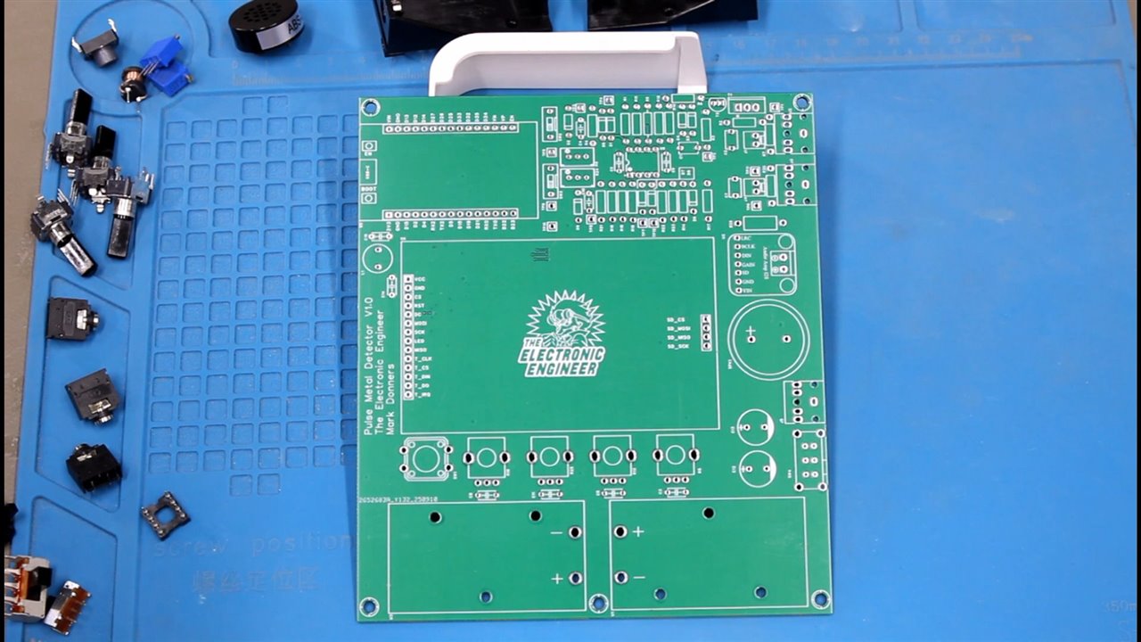

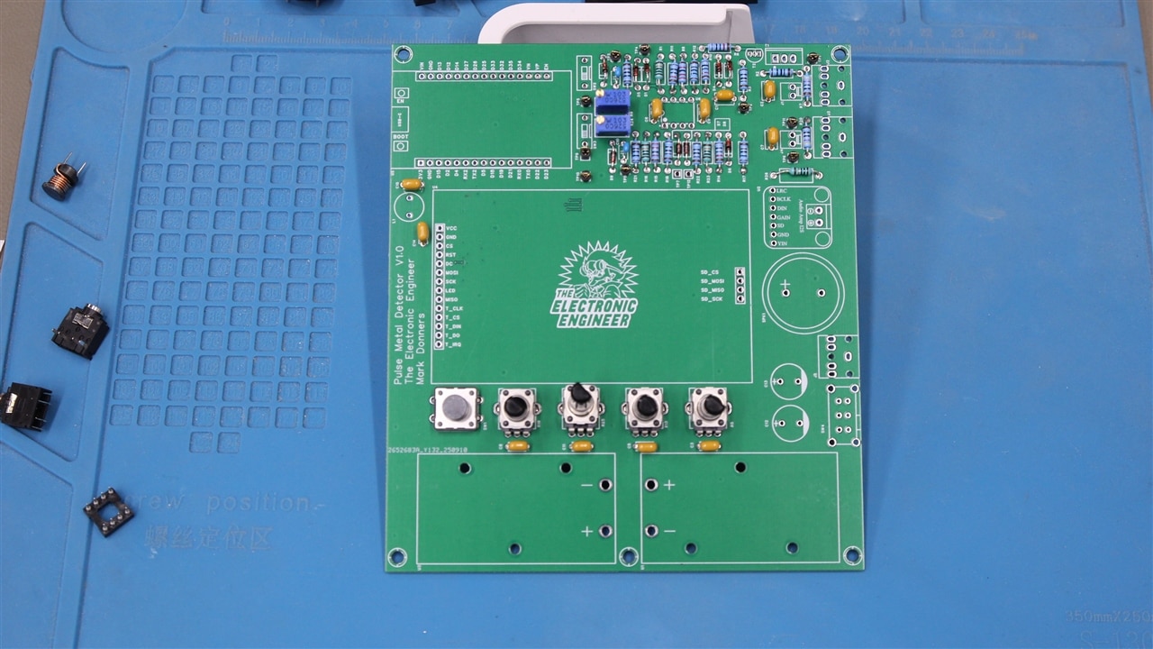
PCB Assembly Approach
Assembly follows a straightforward and reliable process. Mark recommends starting with low-profile components such as resistors, then moving on to capacitors and connectors, and finally installing sensitive parts like the ESP32, display, and audio board.
Throughout the process, careful inspection is important:
“Make sure to inspect the board closely to see that you didn’t make any short circuits when soldering.”
Coil Design and Winding
The coils are central to detector performance, so Mark chose to wind them by hand.
Small Coil
-
Wound on a 125 mm sewer pipe cap
-
Approximately 120 turns of copper wire
Large Coil
-
Wound using a custom 3D-printed mold
-
Includes a brim to keep the wire in place
-
Also approximately 120 turns
The process requires patience, especially when keeping the windings even:
“It’s kind of tricky, but with a little practice, you can get the hang of it.”
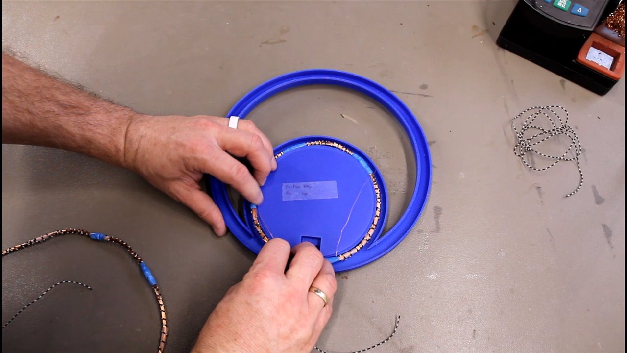
Coil Shielding
To reduce false detection caused by static ground effects, Mark adds a simple shield to each coil. A single wire is spiralled around the coil but left open at one end.
This detail is important:
“Do not close that loop. Because if you close that loop, the shielding will be a real shielding. It will affect the coil, and it cannot detect anymore.”
The open-ended shield reduces interference without blocking the magnetic field used for detection.
Housing and Mechanical Construction
The coils are mounted in a 3D-printed housing and connected using standard audio jacks, making them easy to swap and test. For the detector shaft, Mark reused an old crutch:
“I used an old crutch that I had from an injury. Recycled engineering.”
At this stage, the enclosure is kept easy to open so the coils and wiring can be adjusted later if needed.
Firmware Overview
For the firmware, Mark experimented with using ChatGPT as a coding assistant. He provided the hardware description and desired behaviour, then iterated on the generated code until it matched the system.
“I used ChatGPT as a tool to write this code… checking it, verifying if it works, and doing many iterations to get where I am now.”
The final Arduino sketch is heavily commented to make it easier to follow.
Setup and Calibration
On startup, the firmware initialises the ESP32 peripherals, display, and audio output. It also performs a field calibration and stores reference values in EEPROM so the detector behaves consistently between power cycles.
Main Detection Loop
During normal operation, the firmware:
-
Reads the user controls
-
Generates a pulse
-
Waits for the blanking period
-
Samples the coil response
-
Processes the data
-
Updates the display and audio output
A simplified section of the code illustrates the core behaviour:
// Generate pulse
 digitalWrite(PULSE_PIN, HIGH);
 delayMicroseconds(pulseWidth);
 digitalWrite(PULSE_PIN, LOW);

// Wait before listening
 delayMicroseconds(blankingTime);

// Sample coil response
 adcValue = analogRead(COIL_ADC_PIN);
Using the Metal Detector
Pulse induction detectors rely on changes in the signal, so movement is important. Either the detector or the target must move for reliable detection.
As Mark explains:
“Movement is needed for it to detect metal properly.”
Users are encouraged to adjust the controls while holding a piece of metal near the coil to see how different settings affect sensitivity and response.

Overall
This project combines theory and practical electronics in a way that is easy to explore and adapt. By building the coils, designing the analog circuitry, and tuning the firmware, users gain a clear understanding of how pulse induction metal detectors work. The result is a flexible ESP32-based detector that can be adjusted, refined, and extended as experience grows.
Supporting Links and Downloads
- Episode 696 Supporting Files
Bill of Materials
| Product Name | Manufacturer | Quantity | Buy Kit |
|---|---|---|---|
| STARTECH USB Cable, Type A Plug to Type C Plug, 1 m, 3.3 ft, USB 2.0, Black | STARTECH | 1 | Buy Now |
| NEOHM - TE CONNECTIVITY Through Hole Resistor, 100 kohm, LR Series, 600 mW, ± 1%, Axial Leaded, 350 V | NEOHM - TE CONNECTIVITY | 10 | Buy Now |
| ONSEMI Small Signal Diode, Single, 100 V, 200 mA, 1 V, 4 ns, 4 A | ONSEMI | 10 | Buy Now |
| ALPS ALPINE Rotary Potentiometer, 100 kohm, 1 Turns, Linear, 50 mW, ± 20%, RK09 Series | ALPS ALPINE | 4 | Buy Now |
| VISHAY Power MOSFET, P Channel, 200 V, 6.5 A, 0.8 ohm, TO-220AB, Through Hole | VISHAY | 3 | Buy Now |
| TEXAS INSTRUMENTS Operational Amplifier, 2 Channels, 1 MHz, 0.1 V/µs, 3V to 32V, DIP, 8 Pins | TEXAS INSTRUMENTS | 2 | Buy Now |
| KEMET Multilayer Ceramic Capacitor, 0.1 µF, 200 V, ± 5%, Radial Leaded, X8R, 5.08 mm | KEMET | 10 | Buy Now |
| MURATA Multilayer Ceramic Capacitor, 1000 pF, 50 V, ± 5%, Radial Leaded, C0G / NP0, 5 mm | MURATA | 5 | Buy Now |
| MULTICOMP PRO Multilayer Ceramic Capacitor, 1 µF, 50 V, ± 10%, PC Pin, X7R, 5.08 mm | MULTICOMP PRO | 3 | Buy Now |
| PANASONIC Electrolytic Capacitor, 470 µF, 25 V, ± 20%, Radial Leaded, 2000 hours @ 85°C, Polar | PANASONIC | 2 | Buy Now |
| BOURNS Trimmer, Multi Turn, Cermet, Top Adjust, 10 kohm, Through Hole, 25 Turns | BOURNS | 2 | Buy Now |
| MULTICOMP PRO Battery Holder, Through Hole, 1 x PP3 (9V) | MULTICOMP PRO | 2 | Buy Now |
| MULTICOMP PCB Test Point, Pin, Multicomp Colour Coded Through-hole PCB Test Pins, Black, Through Hole Mount | MULTICOMP | 1 | Buy Now |
| ONSEMI Bipolar (BJT) Single Transistor, NPN, 45 V, 100 mA, 1.5 W, TO-92, Through Hole | ONSEMI | 5 | Buy Now |
| ERG COMPONENTS DIP / SIP Switch, Jumper, 1 Circuits, Slide, Through Hole, SPST, 100 V, 1 A | ERG COMPONENTS | 2 | Buy Now |
| NIDEC COMPONENTS Slide Switch, Sub-Miniature, DPDT, On-On, Through Hole, MFS Series, 1 A, 125 V | NIDEC COMPONENTS | 1 | Buy Now |
| WURTH ELEKTRONIK Tactile Switch, WS-TATV Series, Top Actuated, Through Hole, Round Button, 160 gf, 50mA at 12VDC | WURTH ELEKTRONIK | 10 | Buy Now |
| MULTICOMP PRO Speaker, 150 mW, 8 ohm, 73 dB, 700 Hz to 4 kHz | MULTICOMP PRO | 1 | Buy Now |
| MULTICOMP PRO Inductor, MCSCH895 Series, 3.3 µH, 6.3 A, 0.013 ohm, ± 20% | MULTICOMP PRO | 5 | Buy Now |
| VISHAY Through Hole Resistor, 100 kohm, MRS25 Series, 600 mW, ± 1%, Axial Leaded, 350 V | VISHAY | 10 | Buy Now |
| VISHAY Through Hole Resistor, 10 kohm, MRS25 Series, 600 mW, ± 1%, Axial Leaded, 350 V | VISHAY | 10 | Buy Now |
| VISHAY Through Hole Resistor, 1 kohm, MRS25 Series, 600 mW, ± 1%, Axial Leaded, 350 V | VISHAY | 10 | Buy Now |
| VISHAY Through Hole Resistor, 22 kohm, MRS25 Series, 600 mW, ± 1%, Axial Leaded, 350 V | VISHAY | 10 | Buy Now |
| VISHAY Through Hole Resistor, 470 ohm, MRS25 Series, 600 mW, ± 1%, Axial Leaded, 350 V | VISHAY | 10 | Buy Now |
| PUI AUDIO Exciter, 80Hz to 10.5kHz, 8 ohm, 103dBA, 20W, Round, Square Frame, Bare Mount | PUI AUDIO | 1 | Buy Now |
Additional Parts
| Product Name | Manufacturer | Quantity |
|---|---|---|
| 3d printed parts( files include) | ||
| Wires | ||
| Audio cord stereo jack 3,5mm both sides | ||
| Thin copper wire 0,2mm | ||
| ESP32 DoitDevKit one | ||
| Display | ||
| Audio Board | ||
| PCB-> use the gerber files to order your own pcb at your prefered supplier |


