

.jpg)
In this project, Milos builds a mobile smart cabinet for his 3D printer, filament dryer, tools, and filament storage, combining workshop organisation with safety and monitoring. The cabinet uses a Raspberry Pi and Raspberry Pi Pico to control relays, measure power consumption with current transformers, and monitor temperature and humidity using DHT22 sensors. All data is published over MQTT and visualised in a Node-RED dashboard, with remote power control and live camera monitoring. The result is a practical upgrade for any 3D printing workspace, showing how electronics, software, and physical design can come together to create a safer and more controlled printing setup.
Watch Milos Build the Cabinet!
In this project, Milos set out to build a dedicated home for his 3D printer, filament dryer, tools, and a growing collection of filament spools. Having started with 3D printing in 2020, the technology has since become central to his electronics work, which resulted in 50–60 partially used spools accumulating around his workspace. The solution was a single cabinet that could store everything in one place, with the added requirement that it should be both smart and safe.
As Milos explains in the video, the goal was not just storage:
“We’re going to make it smart. We’re going to make it super safe using an RCD, fuses, turning it on or off using relays… and we’re going to make a user interface to control everything through a web page.”
Idea and Planning
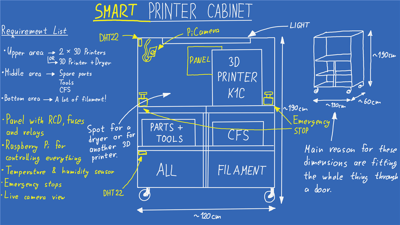
The initial concept was a cabinet built from OSB and wooden planks, large enough to house two 3D printers on the top (or a printer and a filament dryer), with space below for tools, spare parts, a multi-material unit, and filament storage. Two practical constraints shaped the design early on:
-
The cabinet needed to be fully mobile, so it was mounted on caster wheels.
-
Its dimensions had to allow it to pass through a standard doorway, making it easy to relocate within or between workshops.
To plan the layout, Milos created a simple design drawing that divided the cabinet into three vertical zones: printers at the top, tools and accessories in the middle, and filament storage at the bottom. Lighting was also included to improve visibility when working on the printers.
At this stage, the design focused purely on the physical structure. The smart features were intentionally deferred until the cabinet itself was complete.
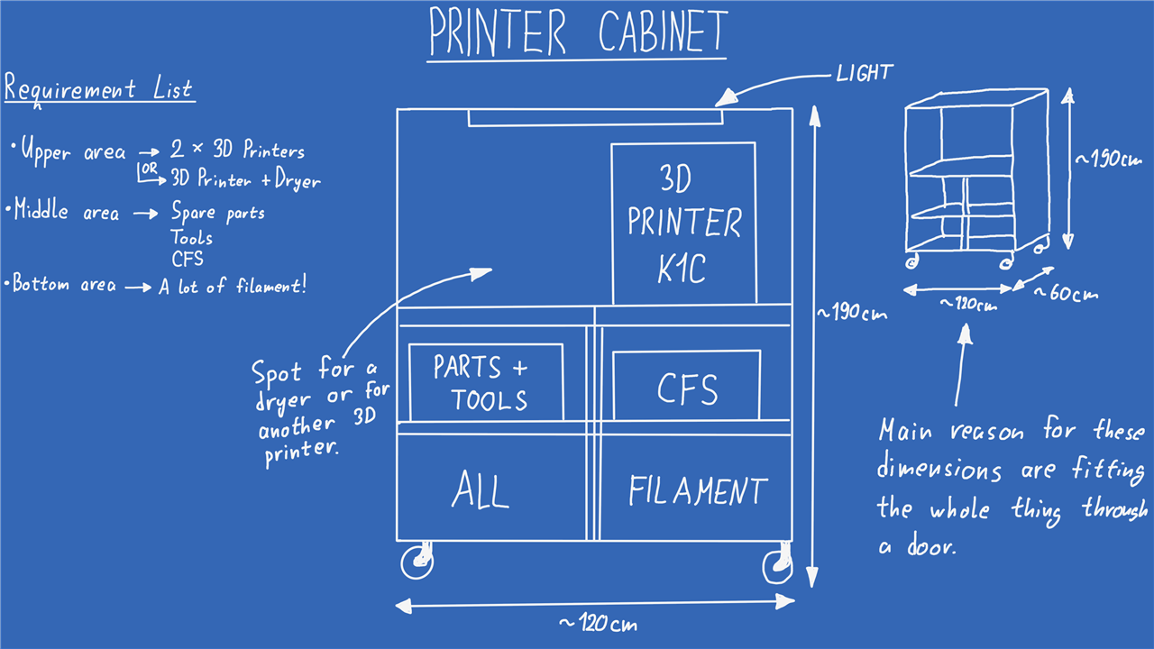
As you can see from the drawing, it lacks any smart features, at least for now. The first thing that had to be done before the smart features was making the whole thing. As good luck would have it, Milos started working on this project mid August, which meant the weather outside was wonderful where he lived. In the video there is a short timelapse showing the whole process, but it took him just under a day from the first cut of the OSB boards to somehow lowering the whole thing down to the ground. A note from Milos is that the whole thing turned out to be way heavier than he initially anticipated!
Building the Cabinet
The cabinet was built from 15 mm OSB sheets and structural timber, with three primary vertical zones:
-
Top: One or two 3D printers, or a printer and filament dryer
-
Middle: Tools, spare parts, and the printer’s multi-material unit
-
Bottom: Filament storage (50–60 spools, with room for expansion)
Two constraints strongly influenced the design:
-
The cabinet needed to be mounted on caster wheels so it could be repositioned or relocated.
-
The overall dimensions had to allow it to pass through a standard doorway.
A simple layout drawing was created to confirm clearances and internal spacing before construction began. Smart features were deliberately excluded from the initial build so that the physical structure could be completed first.
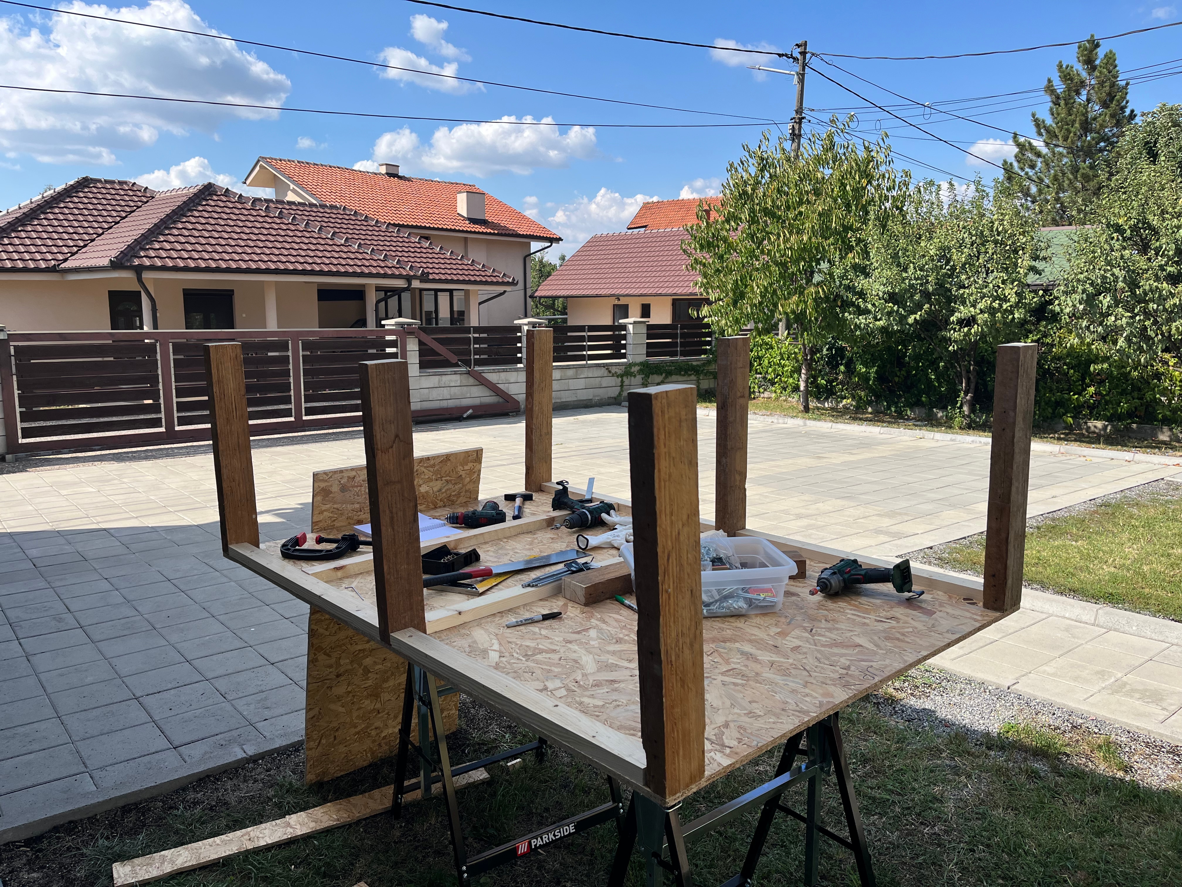
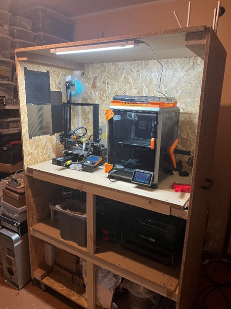
He added two handles to the sides of the cabinet and then managed to drag it through two pairs of doors with a bit of elbow grease! While this was fun, an even better part started with this finished, packing up everything into the cabinet to have it all in one place, this of course included the giant armada of Benchies that finally got a proper place to live!
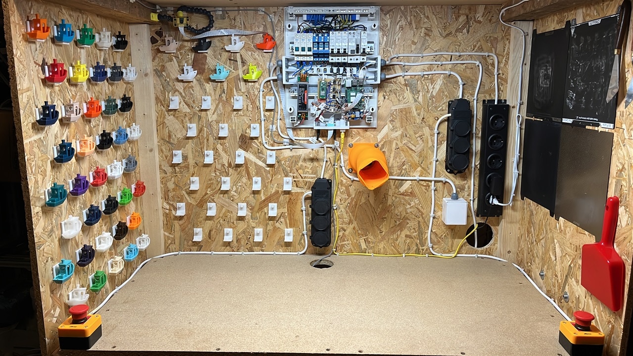
Making the Cabinet Smart
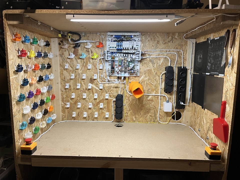
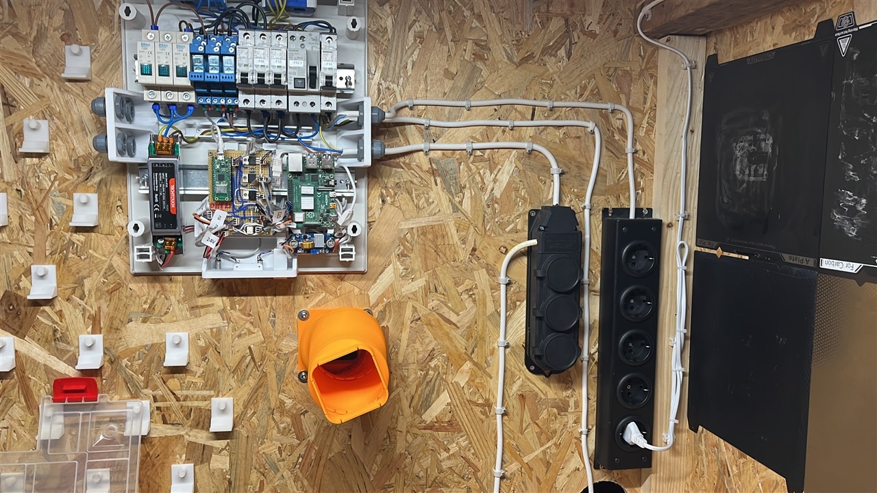
With the mechanical build complete, attention shifted to electronics and safety. Milos began with a detailed wiring and system diagram to define how power, control, and sensing would be handled.
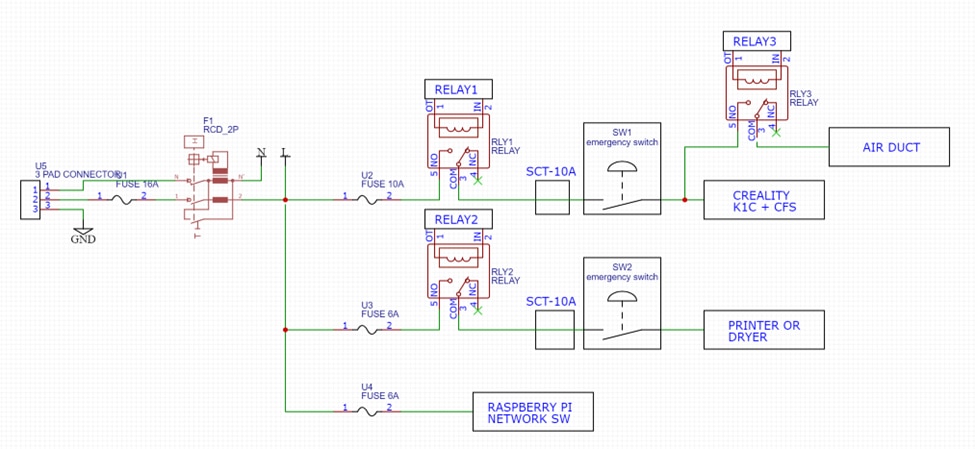
The electrical system includes:
-
A main fuse and RCD for protection.
-
Individual circuit breakers for each printer.
-
Relays to allow remote power control.
-
Emergency stop buttons mounted behind the printers.
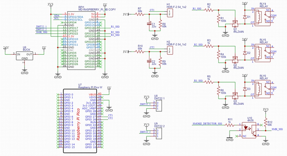
A Raspberry Pi 4 acts as the main controller, handling data collection, relay control, and the user interface. To monitor environmental conditions, two DHT22 temperature and humidity sensors were installed: one in the upper printer area and one in the lower filament storage area. This reflects Milos’ concern that filament performance can degrade in high-humidity environments.

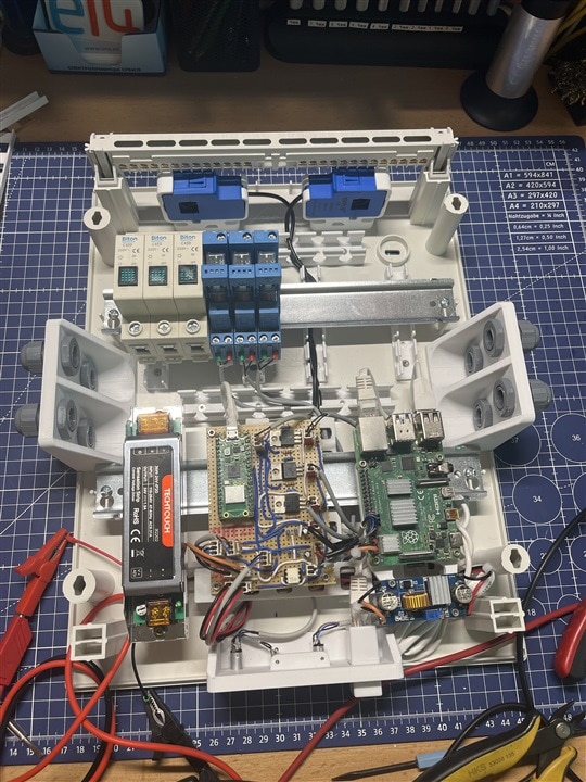
For the environmental sensors he went with the well known DHT22 sensors since they were easy to implement, while for the power measurement, he had to do a bit of experimenting. The plan was to use CTs (Current transformers) which are non-invasive clamps that can be put around the wire to measure the current through it. Since the Raspberry Pi 4 doesn’t have an ADC, he first tried using an I2C ADC (ADS1115), but since he had to get the RMS voltage reading, the ADS1115 just wasn’t fast enough for the task. It couldn’t handle one CT, let alone two that Milos was planning on using for this project. Instead, he stuck with the Raspberry family and used a Raspberry Pi Pico with its onboard 12bit ADC that he programmed to measure the RMS voltage from both CTs and send that data over Serial to the Raspberry Pi 4B.
Measuring Power Consumption
One of the more challenging aspects of the project was measuring power usage safely and accurately. Milos chose non-invasive current transformers (CTs) that clamp around live wires. Initially, an external I²C ADC was tested, but it proved too slow to capture reliable RMS measurements.
Instead, a Raspberry Pi Pico was used, taking advantage of its built-in 12-bit ADC. The Pico firmware samples the CT signals, calculates RMS current values, and sends the results over serial to the Raspberry Pi 4. As Milos notes in the video, this approach proved fast and reliable enough to track real-time current changes.
On the Raspberry Pi side, a Python script reads the serial data, filters noise at low current levels, calculates estimated power usage, and publishes the results to MQTT topics. These values are then visualised in the user interface.

The Pico firmware samples the CT signal using its 12-bit ADC, removes the DC bias introduced by the measurement circuit, and calculates an RMS value over a fixed sampling window:
const int NUM_SAMPLES = 2000;
float acComponent = voltage - MIDPOINT;
sumSq += acComponent * acComponent;
float vrms = sqrt(sumSq / NUM_SAMPLES);
This approach allows sufficient temporal resolution to track real load changes, something Milos found was not possible with an I²C ADC.
Software Architecture
The software stack is divided into three main parts:
-
Raspberry Pi Pico firmware
Handles ADC sampling and RMS calculations for the current transformers. -
Python services on the Raspberry Pi 4
Several scripts run in parallel:-
Environmental monitoring using DHT22 sensors.
-
System monitoring (CPU temperature, load, memory, and disk usage).
-
Serial data ingestion from the Pico and publishing of current and power readings.
-
Camera streaming using the Raspberry Pi Camera, exposed as an MJPEG stream.
For example, system metrics such as CPU temperature and memory usage are periodically published to MQTT, allowing them to be displayed and logged without overloading the main interface.
-
-
Node-RED dashboard
Node-RED subscribes to all relevant MQTT topics and provides a single web-based interface. From here, the user can:-
View live camera feeds.
-
Monitor temperature, humidity, and power consumption.
-
Toggle relays to turn printers and peripherals on or off.
-
Track longer-term trends such as environmental changes and Raspberry Pi performance.
-
As Milos describes it, the aim was to have “everything in one master terminal,” rather than switching between multiple tools and interfaces.
On the Raspberry Pi, a Python script (picy_ct.py) reads the serial stream, extracts current values using a regular expression, and applies noise filtering before publishing data to MQTT:
if ct1 < 0.500: ct1 = 0
if ct2 < 0.150: ct2 = 0
pw1 = ct1 * 230
Low-current readings are explicitly clamped to zero to suppress noise, and power is derived using a fixed 230 V mains reference. These thresholds were tuned during bench testing and reflect the practical limits of the CTs used.
The environmental monitoring script (dht22_script.py) reads the sensors sequentially to avoid timing conflicts and publishes four MQTT topics:
-
Top temperature
-
Top humidity
-
Bottom temperature
-
Bottom humidity
Read failures are explicitly caught and ignored, preventing sensor glitches from disrupting the rest of the system.
This data later revealed measurable temperature differences between compartments during printing, as well as consistently high ambient humidity in the filament area.
Raspberry Pi System Monitoring
In addition to cabinet-specific sensors, the Raspberry Pi monitors its own health using a dedicated script (rp_info.py). This includes:
-
CPU temperature (read directly from
/sys/class/thermal) -
CPU usage and frequency
-
Memory and disk usage
-
Load average and uptime
Each parameter is published to MQTT and displayed alongside cabinet data in the Node-RED dashboard. This makes it possible to spot thermal or resource issues on the control system itself during long print jobs.
Camera Streaming and Visual Monitoring
A Raspberry Pi Camera provides live video monitoring of the cabinet. Rather than relying on a pre-packaged streaming solution, Milos implemented a custom Flask-based MJPEG server (camera_stream_fixed.py).
Key design choices include:
-
Real-time MJPEG streaming for easy embedding in Node-RED
-
Image correction using CLAHE and gamma adjustment to improve visibility
-
A lightweight HTTP endpoint that behaves like an IP camera
The resulting stream can be embedded directly into the dashboard, alongside printer controls and sensor readouts.
Node-RED Dashboard and MQTT Integration
Node-RED acts as the user-facing layer of the system. All sensor data, system metrics, and control signals are exchanged via MQTT topics.
From the dashboard, the user can:
-
Toggle relays to power printers and peripherals
-
View live camera feeds
-
Monitor temperature, humidity, and power consumption in real time
-
Inspect longer-term trends such as Raspberry Pi CPU temperature or filament storage humidity
As Milos describes it, the intention was to avoid fragmented tools and instead provide “one master terminal” for the entire cabinet.
Installation and Testing
Before final installation, the entire system was tested on the bench using a heater as a known load. This allowed the current measurement system, relays, RCD, and emergency stops to be validated safely.
This validated:
-
RCD operation
-
Relay switching
-
Emergency stop functionality
-
Current measurement accuracy
After installation, extended tests confirmed stable operation. Power consumption during printing typically remained below 200 W, while sensor data highlighted humidity levels high enough to justify careful filament storage.
One limitation identified was increased noise from a higher-rated (50 A) CT, which was mitigated in software by applying stricter thresholds.
Once installed in the cabinet, further testing showed clear temperature differences between the upper and lower compartments when the printer was running, as well as consistently high humidity in the filament storage area. Power monitoring confirmed that typical printer operation stayed below 200 W, while also revealing noise issues with a higher-rated CT, which Milos mitigated in software by applying thresholds.
Finished Project
The completed cabinet houses the printer, filament dryer, electronics panel, sensors, and storage exactly as planned. All safety features function as intended, including the emergency stop buttons and RCD protection. The cabinet is fully mobile, remotely controllable, and provides clear insight into environmental conditions and power usage.
With the project complete, Milos notes that while there are small improvements he would make in future revisions, the system already meets its core goals of safety, organisation, and visibility. For those interested in building something similar, all supporting files and additional resources are available below!
Supporting Links and Files
Bill of Materials
| Product Name | Manufacturer | Quantity | Buy Kit |
|---|---|---|---|
| Raspberry Pi 4B - RPI4-MODBP-8GB | RASPBERRY | 1 | Buy Now |
| Raspberry Pi Camera Module V3 - PiCamera V3 | RASPBERRY | 1 | Buy Now |
| RCD - AUR1-40A | PRO ELEC | 1 | Buy Now |
| Circuit Breaker - AUB7 1P C6A | PRO ELEC | 3 | Buy Now |
| Circuit Breaker - PELB1187 | PRO ELEC | 1 | Buy Now |
| DFROBOT SEN0211 | DFROBOT | 2 | Buy Now |
| DFROBOT SEN0137 | DFROBOT | 2 | Buy Now |
| Relay 4-1415073-1 | SHRACK - TE CONNECTIVITY | 3 | Buy Now |
| MP-LI30-20B24PR2 | MULTICOMP PRO | 1 | Buy Now |
| MOSFET IRLZ44NPBF | INFINEON | 3 | Buy Now |
| RASPBERRY PI PICO | RASPBERRY | 1 | Buy Now |
Additional Parts
| Product Name | Manufacturer | Quantity |
|---|---|---|
| Passive components like resistors and capacitors | ||
| Wires, cables rated for 220V | ||
| Power Distribution Box | ||
| OSB 15mm thick plates | ||
| 30x50mm planks | ||
| 40x90mm planks |

