

In this project, Clem builds GimmeGPIO, a compact USB-to-GPIO board that brings Raspberry Pi–style GPIO to almost any computer. Using an ESP32-S2 and a Pi-compatible header, the board lets laptops, desktops, and even older machines interact with real-world hardware over USB. Clem walks through the hardware design, thin PCB choices, firmware approach, and Python control, showing how GPIO, PWM, I2C, and serial can be added without relying on a Raspberry Pi.
Watch the Project
Clem’s GimmeGPIO project starts from a familiar frustration. Full-sized computers are powerful, flexible, and often already sitting on a desk, but they are cut off from direct hardware control. GPIO is the missing link. GimmeGPIO is Clem’s answer to that gap: a small USB-connected board that gives almost any computer access to Raspberry Pi-style GPIO, without turning the computer itself into a single-board system.
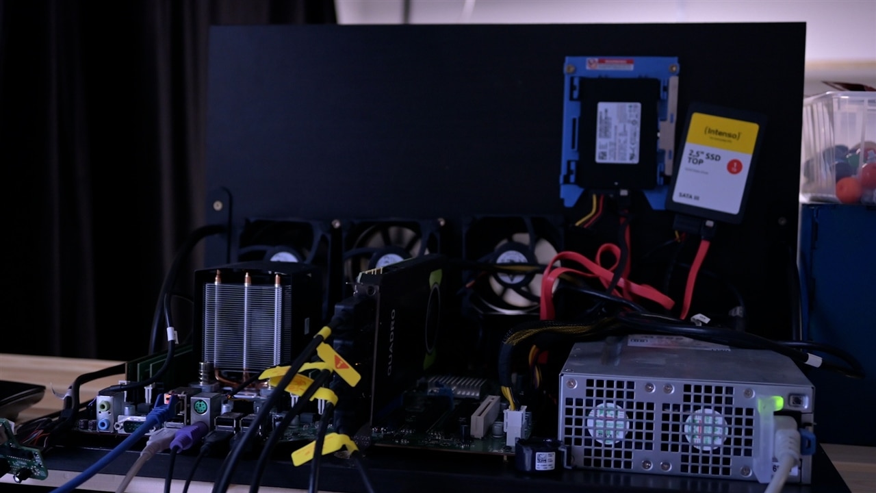
The project is not positioned as a Raspberry Pi replacement. Instead, it is a way to reuse older laptops, desktops, or even servers for hardware projects, or to add more GPIO to an existing setup when a Pi alone is not enough.
Why GPIO Matters
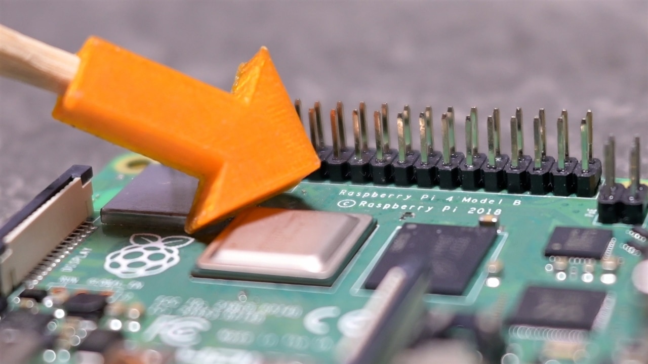
Early in the video, Clem frames the problem very directly. The real difference between a Raspberry Pi and a typical computer is not performance, storage, or operating system. It is the GPIO pins. Those pins are what let software interact with the physical world. LEDs, relays, sensors, buses, and simple control signals all depend on them. As Clem puts it, GPIO is “basically about putting code into the real world.”
Once you see the problem that way, the solution becomes obvious. Every computer already has one common interface, regardless of age or form factor. USB. Clem leans on that universality, noting that USB has been around since the late 1990s and is effectively guaranteed to be present in some form. GimmeGPIO is therefore built as a USB-to-GPIO bridge, designed from scratch rather than relying on off-the-shelf adapters.
Familiar Shape, Flexible Reality
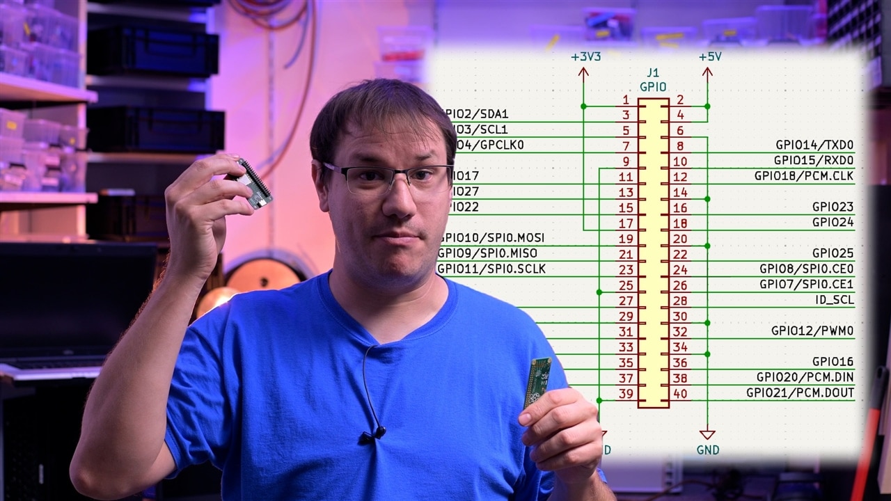
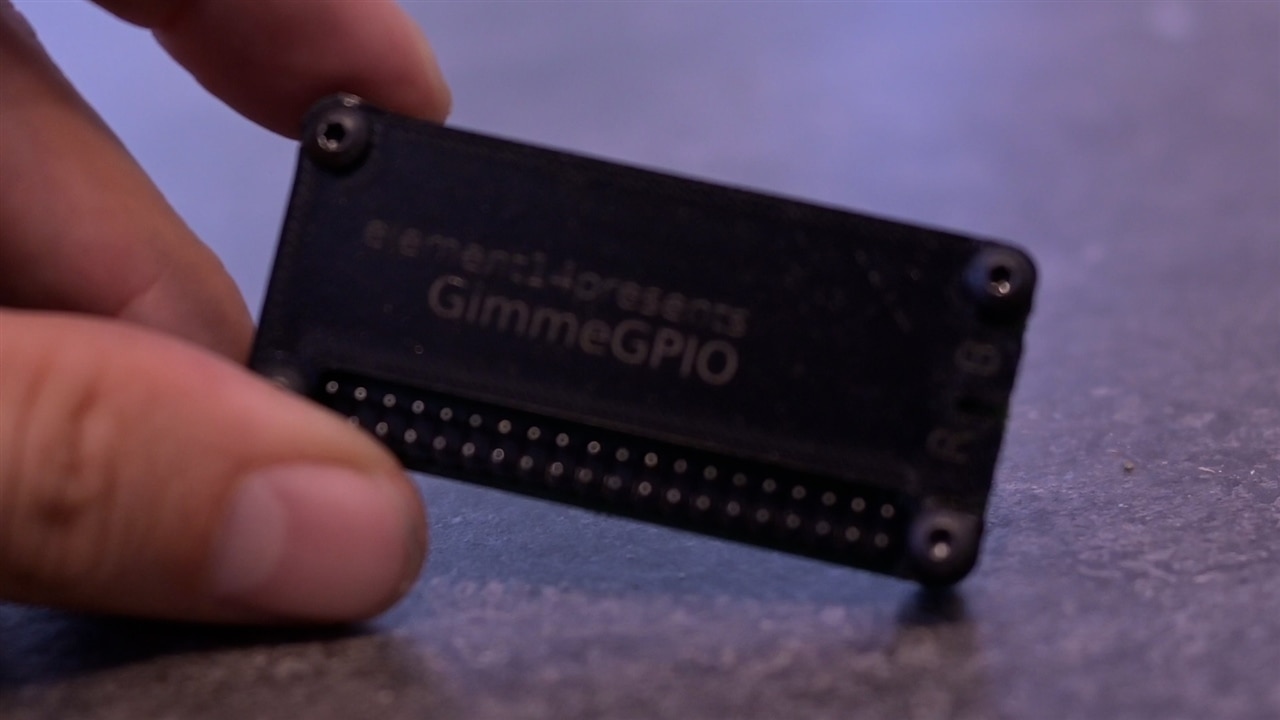
Physically, GimmeGPIO looks immediately familiar. It matches the size, layout, and pin arrangement of a Raspberry Pi Zero. Clem points out that this is intentional. The board follows the same pinout and pin capabilities, which means existing Raspberry Pi documentation, pinout diagrams, and even accessories can be reused without translation.
That familiarity does not mean the design is locked in. Internally, the ESP32-S2’s pin multiplexing means the GPIO functions are not hard-wired to specific pins forever. Clem explains that while the current firmware mirrors the Raspberry Pi layout, the mapping can be changed later if a different layout or feature set makes more sense. The Pi-style header is a convenience, not a constraint.
Hardware Choices and PCB Design
The core of the board is an ESP32-S2. Clem’s reasoning is practical. It provides native USB support, enough GPIO to populate the full header, and still leaves a hardware UART available. That UART matters because it allows serial data to be passed through the board without everything being handled in software.
USB 2.0 ultimately caps performance, but Clem is clear that this is not a real limitation for the kinds of projects GimmeGPIO targets. GPIO, I2C, UART, and PWM rarely demand more bandwidth than USB can comfortably provide.
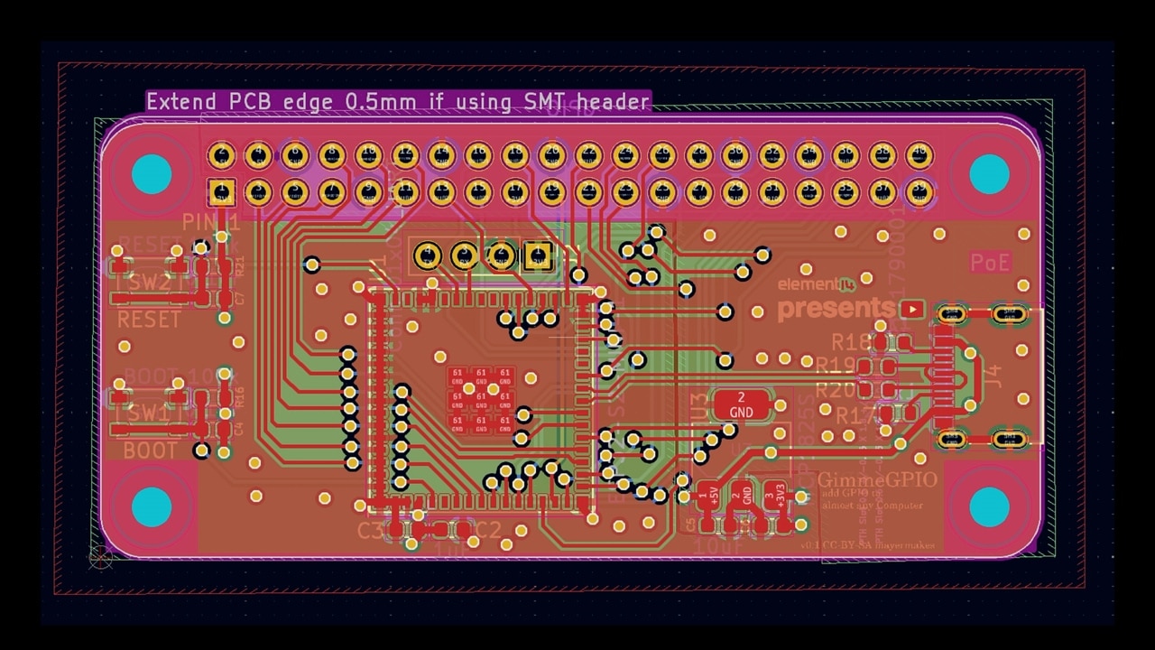
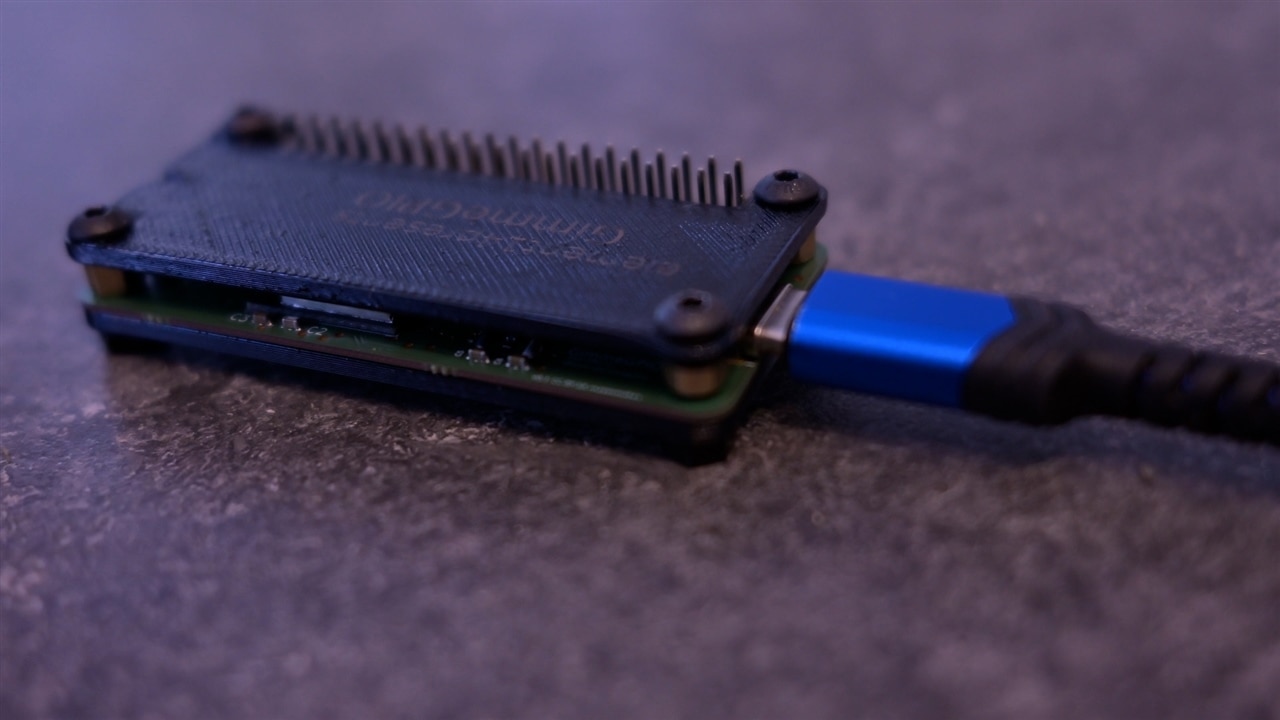
The PCB itself is unusually thin. Manufactured as a four-layer board at 0.8 mm, it is slim enough to be embedded into other hardware. Clem explicitly calls out future possibilities like installing the board inside an old laptop chassis. That thinness comes with a warning, though. During testing, overtightening the enclosure caused the PCB to flex enough to stop working. The takeaway is simple: thin boards are powerful, but they need to be treated gently.
How the Firmware Thinks
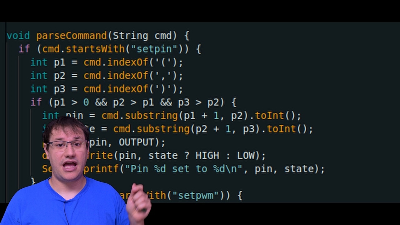
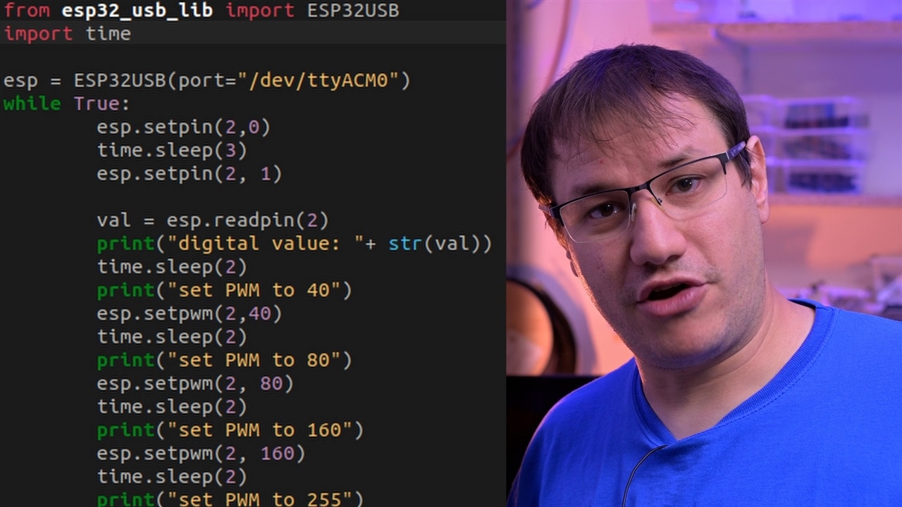
Rather than hiding everything behind opaque firmware, Clem keeps the device simple. GimmeGPIO presents itself as a USB serial device. Commands are sent as short text strings, either manually through a serial terminal or programmatically from code. This makes the system easy to inspect, debug, and extend.
When Clem talks about the code in the video, he focuses less on syntax and more on structure. Each capability has a clear purpose. Digital writes exist to do exactly what you would expect: set a pin high or low. Reads return the current state. Analog reads are supported, with Clem openly acknowledging that analog performance on both older Raspberry Pi boards and the ESP32 is limited. The goal here is parity, not perfection.
PWM output is where the firmware becomes more interesting. Clem uses the ESP32’s LEDC peripheral, which was originally designed for LED brightness control. Because it runs in hardware and continuously generates the waveform, it avoids timing jitter and frees the main processor. Clem mentions that recent changes to the ESP32 Arduino core altered how this peripheral is configured. To make this clear for anyone recreating the project, both the older and newer approaches are left visible in the firmware. His advice is blunt: do not blindly trust random tutorials, especially if they no longer compile.
UART and I2C support follow the same philosophy. The firmware exposes them because the hardware supports them, but Clem is upfront that some parts, particularly serial passthrough, still need refinement. The intent is clear, even if the implementation is still evolving.
Python on the Host Side
To make the board usable from a normal computer, Clem wrote a small Python library. The aim is familiarity rather than cleverness. Python is widely used in the Raspberry Pi ecosystem, so it makes sense to reuse that workflow. From the user’s point of view, the library simply wraps serial communication and turns it into function calls.
Clem’s emphasis here is ease of use. You plug in the board, open a serial port, import the library, and start controlling pins. There is no need to touch the firmware to get started. Experimentation happens on the computer, not on the microcontroller.
Putting It to the Test
In the video, Clem demonstrates the board using both a serial terminal and Python while probing the pins with an oscilloscope. Digital transitions, PWM signals, and fast serial interactions are all shown live. The close spacing of the Raspberry Pi header makes probing slightly awkward, but electrically the signals behave as expected.
Analog input performance is shown with appropriate expectations. Clem notes that analog reading was never a strong point on early Raspberry Pi boards, and the ESP32 behaves similarly. For simple measurements it works, but it is not presented as a precision instrument.
Case, Finish, Firsts and Where This Leads
To make the board usable as a standalone device, Clem designed a simple plate-based enclosure that can be 3D printed or laser cut. This project also includes several personal firsts: using very thin PCBs, engraving black PETG with a fibre laser, and working in a new workshop. These details are not just cosmetic. They highlight that GimmeGPIO is as much an exploration as it is a finished tool.
GimmeGPIO is not framed as a final product. It is a solid, working platform that can grow. The flexible pin mapping, thin PCB, and simple communication model all point toward future variants, including embedded versions. Clem also hints at making more boards simply because there are plenty of old computers that could benefit from GPIO access.
In the end, the project does exactly what it sets out to do. It removes the artificial boundary between general-purpose computers and the physical world. With GimmeGPIO, GPIO is no longer tied to a specific board. It becomes a feature that any computer can have.
Supporting Links and Downloads
- GimmeGPIO Github - Github Snapshot
Bill of Materials
| Product Name | Manufacturer | Quantity | Buy Kit |
|---|---|---|---|
| USB Connector, USB Type C, USB 2.0, Receptacle, 16 Ways, Surface Mount, Through Hole Mount | Molex | 1 | Buy Now |
| Pin Header, Board-to-Board, 2.54 mm, 2 Rows, 40 Contacts, Through Hole | Multicomp pro | 1 | Buy Now |
Additional Parts
| Product Name | Manufacturer | Quantity |
|---|---|---|
| Esp32-s2-mini-u1 | 1 | |
| Random PC with USB port | 1 |
Top Comments