


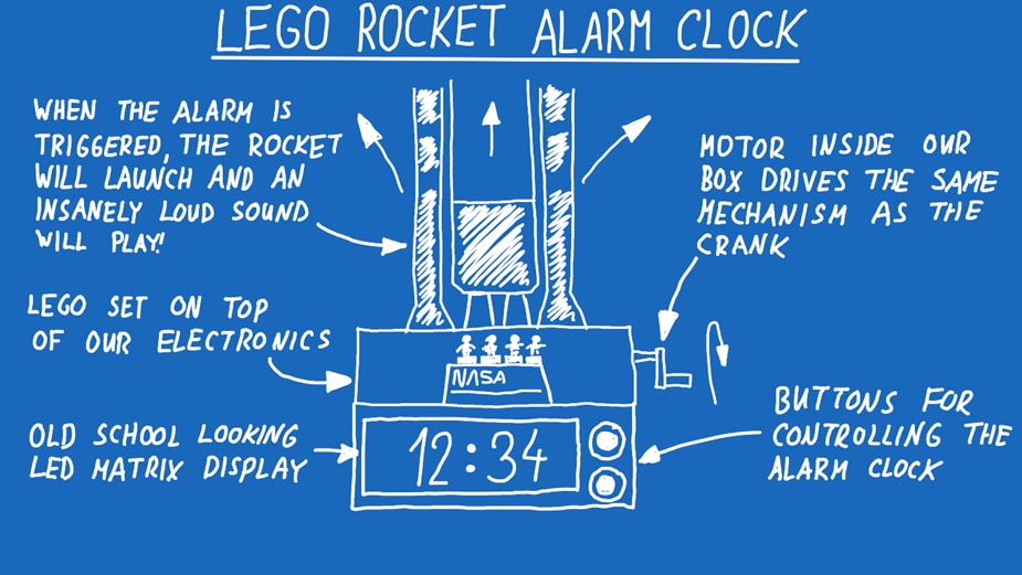
What if your alarm clock launched a rocket instead of playing a gentle tone? In this project, Milos turns the LEGO NASA Artemis SLS into a motorised, Arduino-powered alarm clock that raises the rocket and blasts a megaphone when it’s time to wake up. The build combines a NEMA 17 stepper motor, relays to hack a megaphone, an LED matrix display, Wi-Fi control, and a custom web interface so you can configure everything from your browser.
Watch the Lift-Off!
Building the World’s Loudest LEGO Alarm Clock
When Milos set out to build a new alarm clock, he did not start with typical design constraints like size, comfort, or subtlety. Instead, he started with a simple premise: rockets are among the loudest human-made machines ever created. That idea quickly evolved into a LEGO NASA Artemis rocket that would not just look the part, but behave like a launch sequence every morning.
The result is a project that blends mechanical LEGO engineering, Arduino automation, reverse-engineered consumer electronics, and a web-based control interface.
From Rocket Inspiration to Alarm Clock Concept
The project began with the LEGO NASA Artemis Space Launch System set. While assembling it, Milos discovered a mechanical detail that set the tone for the entire build: a tiny internal gear designed to rattle during operation to mimic the sound of launch vibration. That detail pushed the concept from a simple motorised display to a full alarm clock experience.
In the transcript, Milos reflects on how the idea escalated beyond a simple novelty:
“I wanted something that would actually force me to wake up… something you cannot ignore.”
The design goals quickly became clear:
-
Motorise the LEGO launch mechanism
-
Add a display and controls
-
Create an alarm that is impossible to sleep through
The third requirement became the defining challenge of the project.
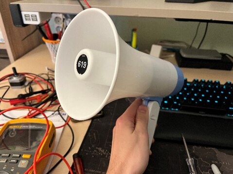
Solving the Sound Problem: The Megaphone Hack
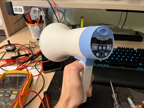
Originally, the plan was to use a megaphone capable of playing MP3 files via USB. The delivered device did not match expectations. Instead of USB playback, it only supported record and playback through a microphone. What initially looked like a setback became one of the project’s most interesting design decisions.
The limitation actually made the system more flexible and tactile. Any sound could be recorded directly into the megaphone and replayed as the alarm. This gave the clock a unique personality and avoided the complexity of integrating audio playback electronics.
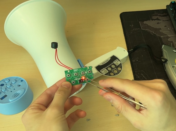
But controlling the megaphone electronically introduced a major obstacle: it was designed for manual button presses.
Milos explains the workaround clearly:
“The megaphone is designed to be used by pressing the buttons… so I soldered wires in parallel with the buttons and used relays to simulate the presses.”
This approach essentially turned the megaphone into a remotely controlled device. The Arduino does not generate audio; it triggers the megaphone’s existing circuitry in the correct sequence. It is a clean example of hardware hacking that avoids reinventing functionality already present in consumer electronics.
Electronics Architecture and Control Strategy
At the center of the build sits an Arduino Uno R4 WiFi. The choice of board was deliberate: the project requires multiple GPIO pins, relay control, motor control, Wi-Fi connectivity, and a web interface.
From the code, the relay pins controlling the megaphone buttons are defined explicitly:
#define RECORD 3
#define PLAY 4
#define TRIGGER 5
#define STOP 6
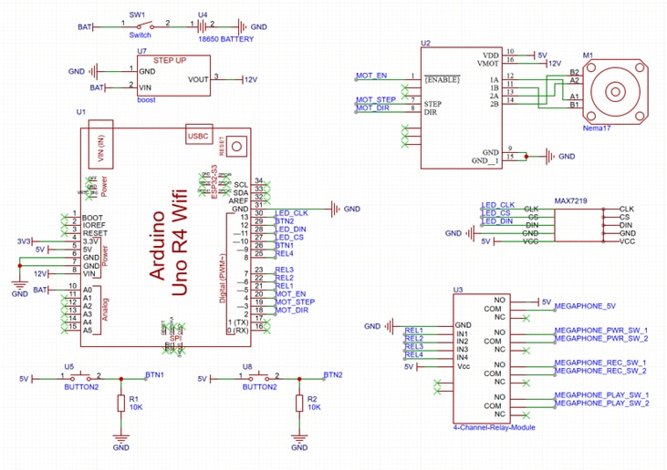
The firmware also defines a complete stepper motor configuration:
#define STEP_PIN 9
#define DIR_PIN 8
#define ENABLE_PIN 7
#define LIMIT_SWITCH_MIN 11
#define LIMIT_SWITCH_MAX 12
The presence of limit switches is a key safety and reliability feature. The mechanism cannot overrun its physical bounds. This is critical for a device that operates unattended every morning.
Milos notes in the transcript how important reliability was:
“This has to work every day without me touching it, otherwise it defeats the purpose of an alarm clock.”
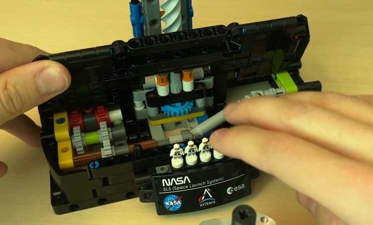
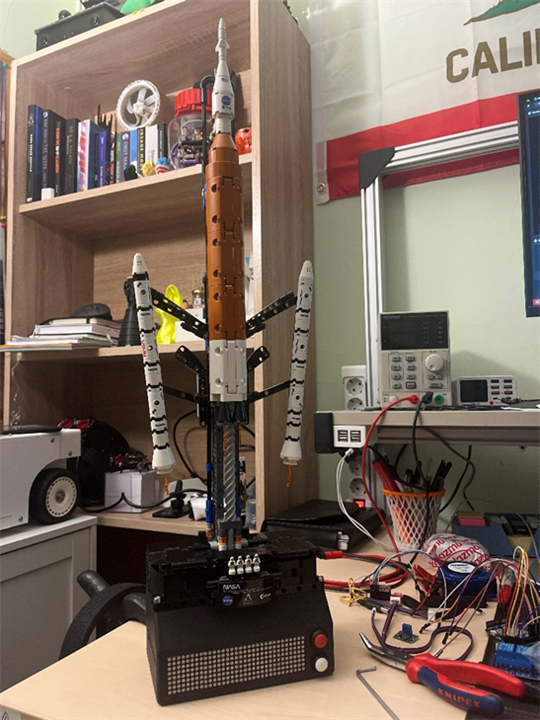
Mechanical Integration: Driving LEGO from Below
One of the most thoughtful aspects of the build is how the motor integrates with the LEGO model.
Rather than mounting the stepper motor visibly on the side, Milos redesigned the drive path so the motor sits beneath the rocket base. He created a 3D-printed coupler that connects a NEMA 17 stepper motor to the LEGO gear train.
This preserves the visual integrity of the LEGO set while still using the original gearing. It also highlights a recurring theme in the project: keep the LEGO aesthetic intact while embedding real engineering underneath.
He explains this design decision in the transcript:
“I didn’t want the motor visible anywhere… everything had to stay hidden under the model.”
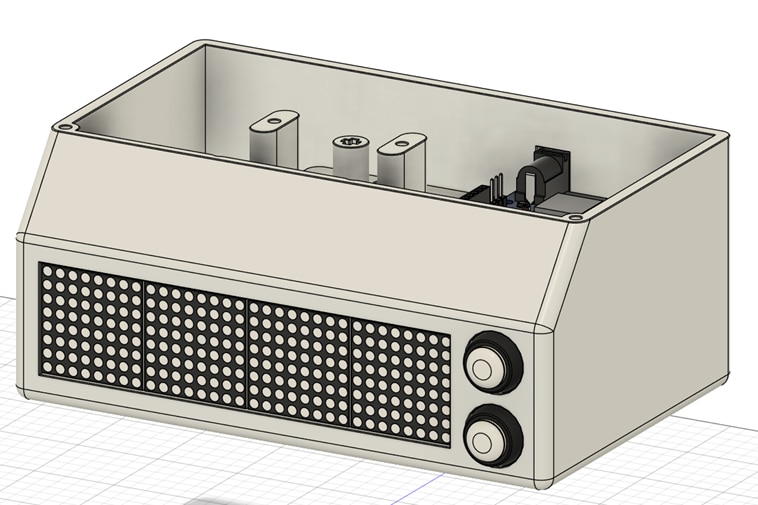
The enclosure itself was printed in black PLA and dimension-ed using LEGO’s standardised spacing, making the mechanical alignment straightforward.
Software Design and Web Interface
The software side of the project is far more sophisticated than a typical Arduino alarm clock. The firmware includes Wi-Fi connectivity and a full web interface.
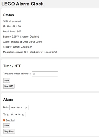
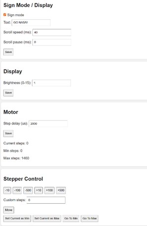
Key features of the firmware include:
-
Static IP configuration for easy access
-
Web-based alarm scheduling
-
Time synchronisation via internet
-
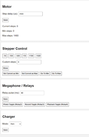
Relay testing and calibration tools
-
Stepper motor min/max configuration
-
LED matrix brightness control
From the code:
#define NTP_SERVER "pool.ntp.org"
#define GMT_OFFSET_SEC 0
#define DAYLIGHT_OFFSET_SEC 3600
This enables automatic time updates using NTP, eliminating the need to manually set the clock.
The web interface is designed to complement physical controls rather than replace them. Physical buttons remain available for emergency silence when the megaphone begins blasting in the morning.
Sequencing the Wake-Up Routine
The firmware reveals how the alarm sequence is orchestrated.
Timing constants define the startup behaviour:
This suggests a carefully choreographed sequence:
-
Trigger megaphone playback via relay sequence
-
Run the stepper motor to animate the rocket mechanism
-
Maintain motion for a fixed duration
-
Allow manual stop if needed
The combination of mechanical motion and amplified audio turns the wake-up routine into a full launch event.
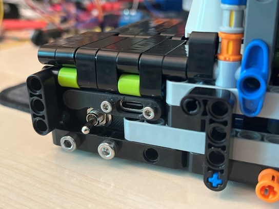
Challenges and Lessons Learned
As the real Artemis mission prepares for launch, Milos discovered that the biggest challenge in building his own morning “launch system” wasn’t the mechanics or the code, it was the wiring. Packing everything neatly into the enclosure turned into the most time-consuming part of the build. As he admits, “The wiring was definitely the most tedious part of the whole project.” That challenge reflects the wider balance he was aiming for: something bold and loud enough to wake you instantly, but reliable enough to run every single day.
The decision to control the megaphone using relays captures that mindset perfectly. Instead of redesigning the megaphone electronics, Milos focused on a practical solution that works consistently and keeps the build approachable for others to recreate.
This isn’t a finished idea either. Milos already sees the project as something to keep evolving. “There are definitely more things I want to add later,” he says, with plans to keep experimenting with the web interface, motion behaviour, sounds, and general refinements to the enclosure and wiring.
Even now, the project works exactly as intended: a dramatic, over-the-top alarm clock inspired by a real rocket launch. With the Artemis mission on the horizon, it feels fitting that this LEGO SLS now delivers its own daily countdown and liftoff on the desk.
Supporting Links and Downloads
Bill of Materials
| Product Name | Manufacturer | Quantity | Buy Kit |
|---|---|---|---|
| Arduino Uno R4 WiFi | Arduino | 1 | Buy Now |
| 4 Channel Relay Module | SEEED Studio | 1 | Buy Now |
| NEMA 17 Stepper Motor - FIT0278 | DFROBOT | 1 | Buy Now |
| Black PLA - MP010755 | MULTICOMP PRO | 1 | Buy Now |
Additional Parts
| Product Name | Manufacturer | Quantity |
|---|---|---|
| SLS LEGO Set - https://www.lego.com/en-us/product/nasa-artemis-space-launch-system-rocket-42221 | ||
| Battery Powererd Megaphone | ||
| Quad LED Matrix Module - MAX7219 | ||
| A4988 Stepper Motor Driver | ||
| A4988 Adapter Board | ||
| Push buttons | ||
| Wires | ||
| Screws M3 and M4 |


