

Clem takes a vintage Z-scale train controller and rebuilds it using modern electronics to achieve smooth, precise speed control. By analysing the original transformer-based controller, he demonstrates why it produces stepped voltage and inconsistent low-speed performance. Clem then builds a proof-of-concept system using an Arduino Uno R4, a motor driver, and a rotary encoder to generate PWM (Pulse Width Modulation) motor control with ramping for smoother acceleration. Along the way he explains how engineers approach proof-of-concept development, how encoder input can replace analogue controls, and how PWM can maintain torque while allowing extremely slow, scale-accurate train movement.
All Aboard!
From Vintage Control to Modern Precision
Clem Mayer has a fascination with small-scale trains, and in this time he sets out to solve a practical problem: how to control a Z-scale locomotive with the kind of precision that modern electronics can offer.
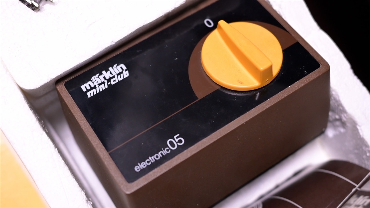
The starting point is a piece of hardware that is almost half a century old, the original controller that came with Clem’s train set. It still works, but it quickly becomes clear that “working” and “working well” are not necessarily the same thing.
Rather than simply replacing it, Clem treats the project as an opportunity to demonstrate a key engineering concept: the proof of concept (PoC). His goal is not only to build a smoother controller for his train, but also to show how engineers test whether an idea is viable before committing to a full design.
As Clem puts it early in the project:
"I'm showing you the proof of concept and what you can actually do with it... by building a super smooth train controller for my new, tiny train!"
Testing the Original Controller
The first step is understanding the existing system.
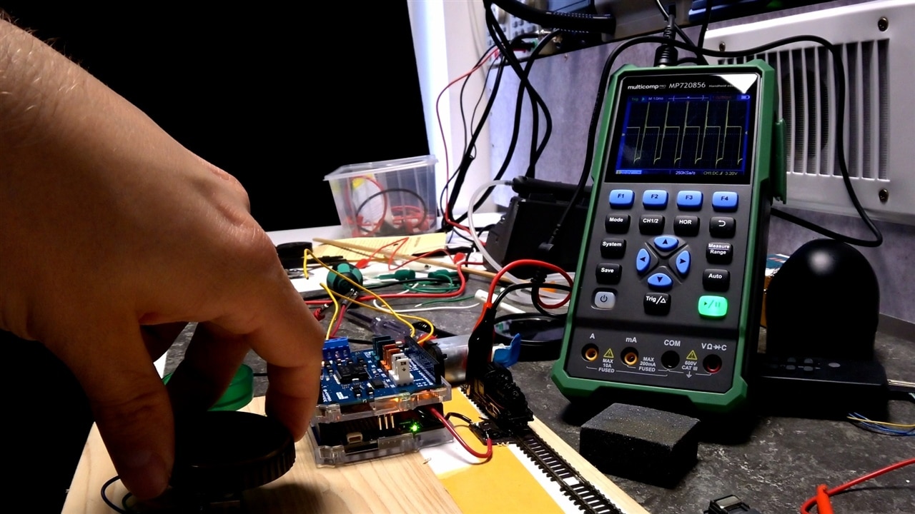
Clem connects the original controller, a variable transformer, to a short 700 mm section of Z-scale track and begins measuring its behaviour with an oscilloscope and a multi-meter. The design is typical of older analogue train controllers: a large dial adjusts the output voltage sent to the rails.
On the surface it looks smooth and continuous, but the measurements reveal several limitations.
Examining the output waveform, Clem observes:
“If I look at the waveform it produces on a scope, I can see it's meant to produce DC, but it's quite ripply.”
More importantly, the apparent analog behaviour is not truly continuous. The voltage changes in discrete steps because the transformer works by selecting different windings.
As Clem explains:
“You are reducing or increasing the number of windings that are active for the output… which is not gradual. It's actually in steps.”
The result is noticeable in practice. Small adjustments to the dial produce no visible response from the locomotive, until suddenly the voltage crosses a threshold and the train jumps into motion.
This makes delicate manoeuvres difficult, especially the kind of slow shunting operations Clem wants to perform with his miniature trains.
“There's no way for me to control my train as softly, smoothly and especially as slow as I want.”
What Is a Proof of Concept?
Rather than jumping straight to a finished design, Clem frames the project as a proof-of-concept exercise.
In engineering terms, a PoC demonstrates whether an idea can work before investing time and resources into a full prototype or product.
Clem breaks the concept down into three simple building blocks:
Input – how the system receives control
Processing – how the system interprets and acts on that control
Output – the physical result produced
As he explains:
“No matter what you're building, you can always boil down the concept of proof of concept into three distinct things. You have an input… something that processes that input… and an output.”
If the three parts work together to achieve the desired result, the concept is proven. If not, the design can be adjusted and tested again until it behaves as intended.

Defining the Output
For Clem, the output goal is very specific.
The train must be capable of moving extremely slowly while still maintaining enough torque to pull wagons around the track. This is particularly important for shunting operations.
“I want this to work at the right scale speed for shunting operations… they are allowed to run about ten kilometres an hour during shunting operations.”
Because the locomotive is Z-scale, approximately 1:220 scale, that translates to extremely slow movement on the test track.
Simply lowering the voltage is not enough. Reduced voltage also reduces torque, which can cause the locomotive to stall.
Instead, Clem decides the solution is to maintain sufficient voltage while controlling the effective power delivered to the motor.
Developing the Input: Choosing the Right Encoder
The next step is selecting a control input.
At first glance, a potentiometer might seem like the obvious solution. However, Clem quickly dismisses that approach.
“If I would use a potentiometer, I would have to dissipate all the power through that potentiometer… I would need a massive potentiometer for that.”
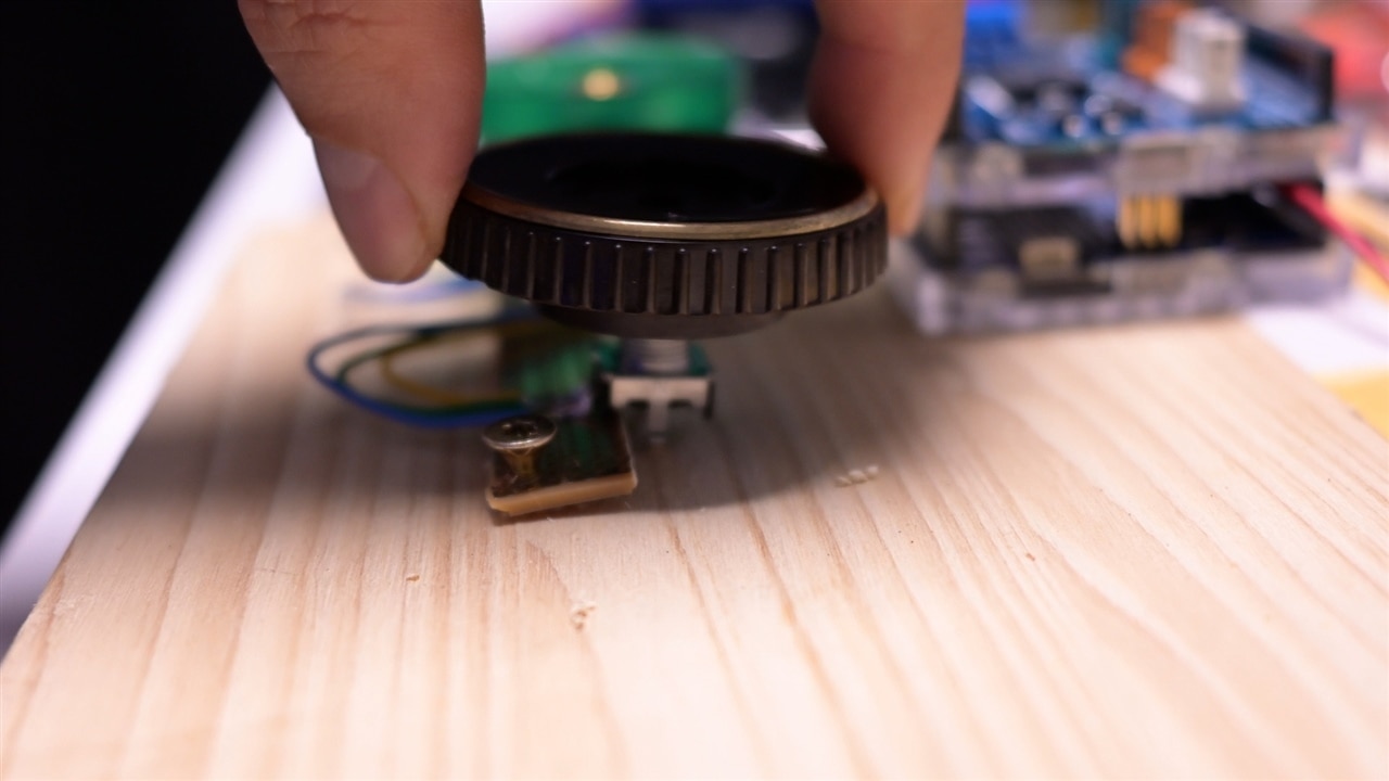
Instead, Clem turns to a rotary encoder.
Unlike a potentiometer, an encoder does not directly regulate power. Instead, it produces digital pulses indicating rotation direction and amount. These signals can then be interpreted by a microcontroller.
“An encoder encodes rotation in a digital way. It only gives a pulse in either direction when I turn it.”
During testing, Clem evaluates two types of encoders:
-
one with tactile detents
-
one that rotates smoothly
Both technically work, but the smooth encoder provides a more natural analog-like feel for fine speed control.
“I want to know which of these feels more natural. That's how I verify the input stage.”

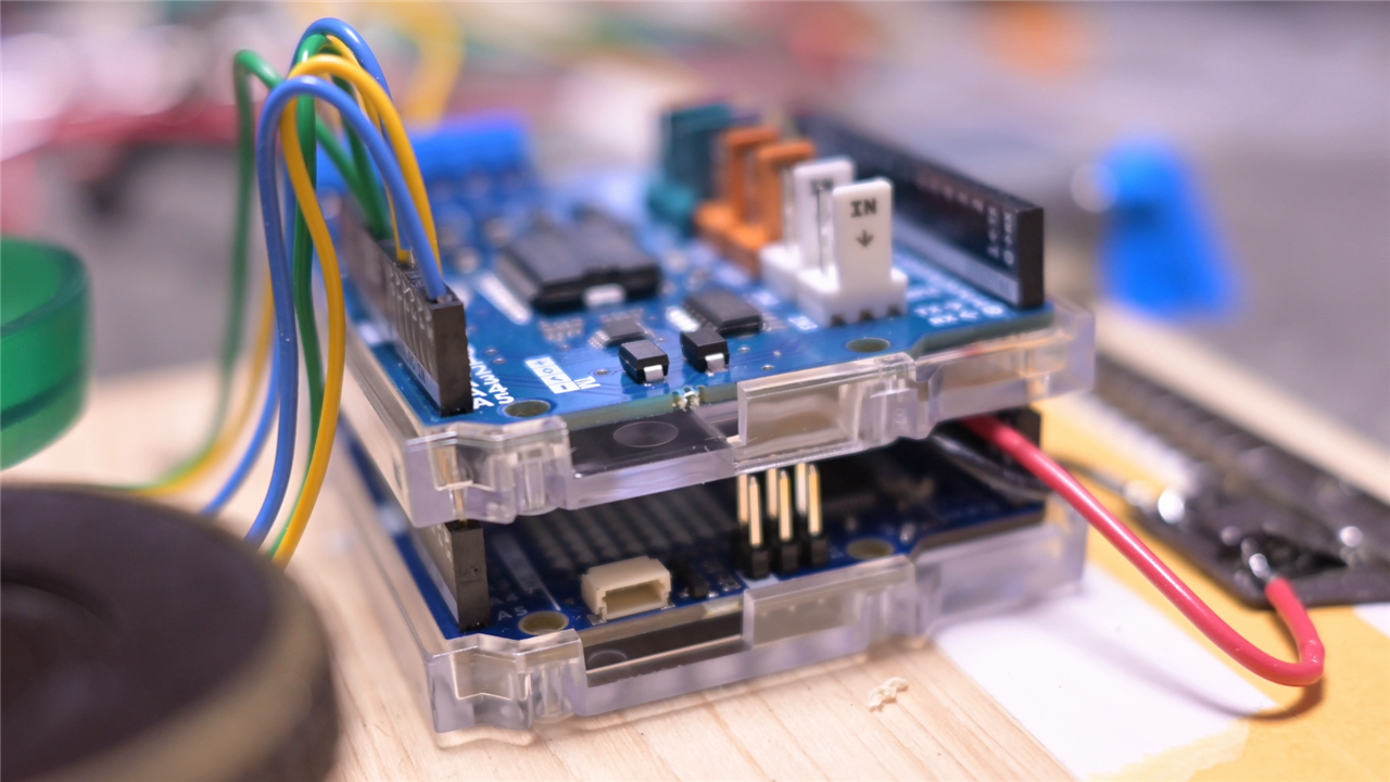
The Processing Stage: Arduino R4 and Motor Shield
To process the encoder signals and control the train, Clem uses an Arduino Uno R4, which is based on a 32-bit Renesas microcontroller.
He notes the distinction deliberately:
“Don't mistake that for the older ones… I'm using an R4, which has a 32-bit Renesas microcontroller.”
The output stage is handled by an Arduino Motor Shield Rev3, built around the classic L298N H-bridge motor driver.
This driver allows the Arduino to control both the direction and speed of the motor by switching power electronically.
As Clem points out, the concept is straightforward:
“A train set in its essence is basically a motor connected to cables that are in the shape of train tracks.”
The controller simply regulates how much power is delivered to that motor.
Understanding the Code
Clem’s prototype software evolves through several stages as he experiments with different control methods.
The initial implementation reads the encoder value and converts it directly into a PWM output.
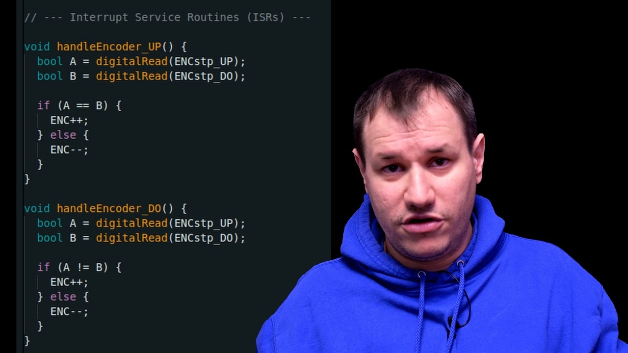
In the code, the encoder count is stored in a shared variable updated through hardware interrupts:
volatile int ENC = 0;
Interrupt service routines detect the encoder’s quadrature signals and update the count accordingly:
void handleEncoder_UP() {
  bool A = digitalRead(ENCstp_UP);
  bool B = digitalRead(ENCstp_DO);

  if (A == B) {
    ENC++;
  } else {
    ENC--;
  }
}
Inside the main loop, the current encoder value determines the direction and PWM output:
if (encCopy > 0) {
  Dir = 1;
  pwm = constrain(encCopy, 0, 255);
} else if (encCopy < 0) {
  Dir = 0;
  pwm = constrain(-encCopy, 0, 255);
}
The PWM signal is then applied to the motor driver:
digitalWrite(DIR_B, Dir);
analogWrite(PWM_B, pwm);
This structure allows the controller to respond instantly to encoder movement.

From PWM to Smooth Control
Clem’s first tests confirm that PWM works for speed control.
“You can now use a higher voltage but still make the train go slow.”
He determines that 9–10 V is an ideal operating range for his locomotives. This provides enough power for older models while remaining safe for newer ones.
However, the direct PWM approach still feels abrupt.
“If I just directly apply the analogWrite… it feels a bit twitchy.”
To improve the behaviour, Clem introduces ramping.
Rather than instantly changing speed, the controller gradually adjusts the PWM output toward the target value. This produces smoother acceleration and braking.
The ramping version of the code implements a non-blocking timing approach:
if (now - lastRampTime >= rampInterval) {
    lastRampTime = now;

    if (lastPwm < pwm) {
        lastPwm = min(lastPwm + rampStep, pwm);
    } else if (lastPwm > pwm) {
        lastPwm = max(lastPwm - rampStep, pwm);
    }

    analogWrite(PWM_A, lastPwm);
    analogWrite(PWM_B, lastPwm);
}
Because the timing is handled with millis() rather than delay(), the program remains responsive while the speed changes.
This non-blocking design ensures that encoder inputs are processed immediately.
Practical Testing Tricks
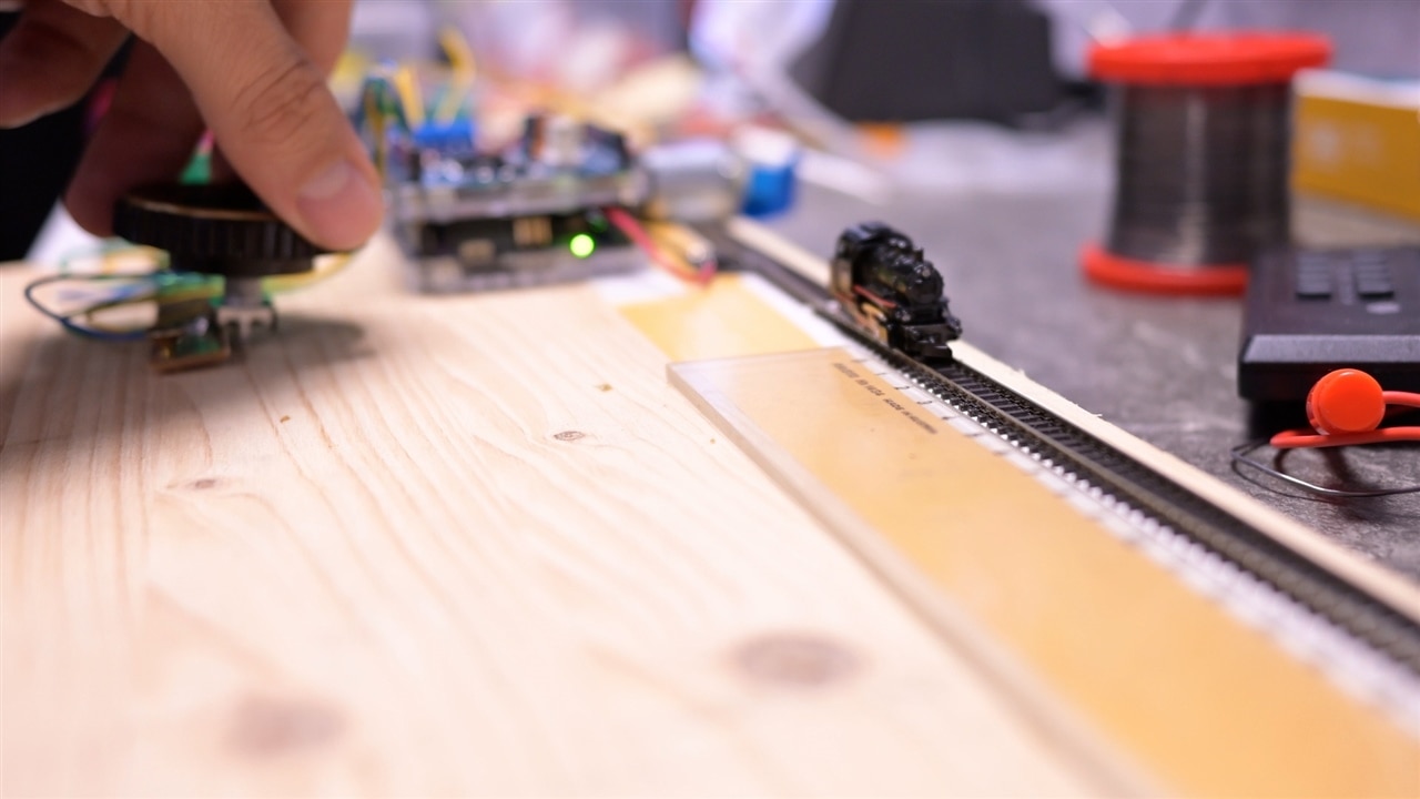
During development Clem builds the entire setup on a simple wooden test board.
To help evaluate PWM behaviour, he adds a second DC motor to the spare channel of the motor driver.
This motor produces audible noise when PWM is applied, allowing Clem to hear changes in the signal even when the train itself has not yet started moving.
“I hear the vibrations of the PWM… so that gives me an indication if the PWM is actually applied.”
It’s a simple but effective debugging method.
Verifying the Output
With the system assembled, Clem tests the controller on his short section of track.
He even attaches a ruler beside the rails to measure how quickly the train travels across the test distance.
“By seeing the little train move along this little piece of track, I can verify my output.”
The improvements are immediately visible.
The locomotive now starts smoothly, moves predictably, and responds proportionally to even small adjustments of the dial.
For Clem, the PoC is complete.

From Concept to Prototype
With the controller working smoothly and predictably, Clem has achieved the goal of the project: proving that the concept works.
The input, processing, and output stages all behave as intended.
That means the next step is clear, turning the proof of concept into a dedicated hardware design.
And thanks to the testing process, Clem now knows exactly how that design should behave.
Supporting Files and Links
Bill of Materials
| Product Name | Manufacturer | Quantity | Buy Kit |
|---|---|---|---|
| EC12E2430804 | ALPS ALPINE | 1 | Buy Now |
| EC11E18244AU | ALPS ALPINE | 1 | Buy Now |
| A000079 | ARDUINO | 1 | Buy Now |
| L298N | STMICROELECTRONICS | 1 | Buy Now |
| ABX00087 | ARDUINO | 1 | Buy Now |
| MP720783 | Multicomp pro | 1 | Buy Now |
Additional Parts
| Product Name | Manufacturer | Quantity |
|---|---|---|
| Model Train Set | N/A | 1 |
