


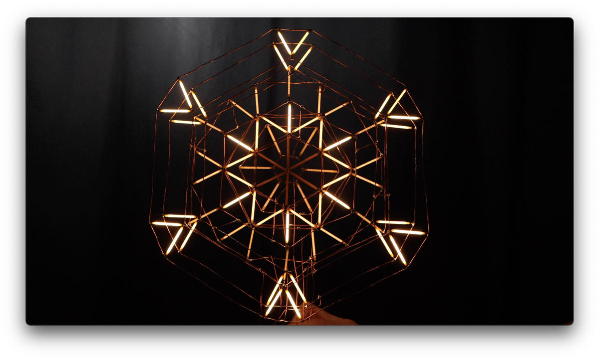
Natasha builds a free standing LED snowflake using LED filament, exploring how to shape, wire, and solder a layered circuit sculpture from scratch. From planning segmented control to handling fragile components, this project walks through the full process and what she learned along the way.
Watch the Build
Inspiration and a Cold Start
The project started with a small LED snowflake produced out of LED filament (or LED noodles) that Natasha came across that she wanted to make at a much larger scale. The other goal, inspired by the Saks Fifth Avenue holiday light show in New York, was to have the snowflake animate in segments rather than just illuminate as a single unit. That annual show has been running since 2004, projecting choreographed light sequences across the store's Midtown Manhattan facade using over 70,000 LEDs across 450 lighting cues. That kind of layered, breathing animation is what Natasha was working toward with her sculpture.
She also wanted this to be the project where she figured out how to do circuit sculpture properly: connecting components with bare wire, no PCB, no enclosure, everything visible.
The Material: LED Filament "Sticks"
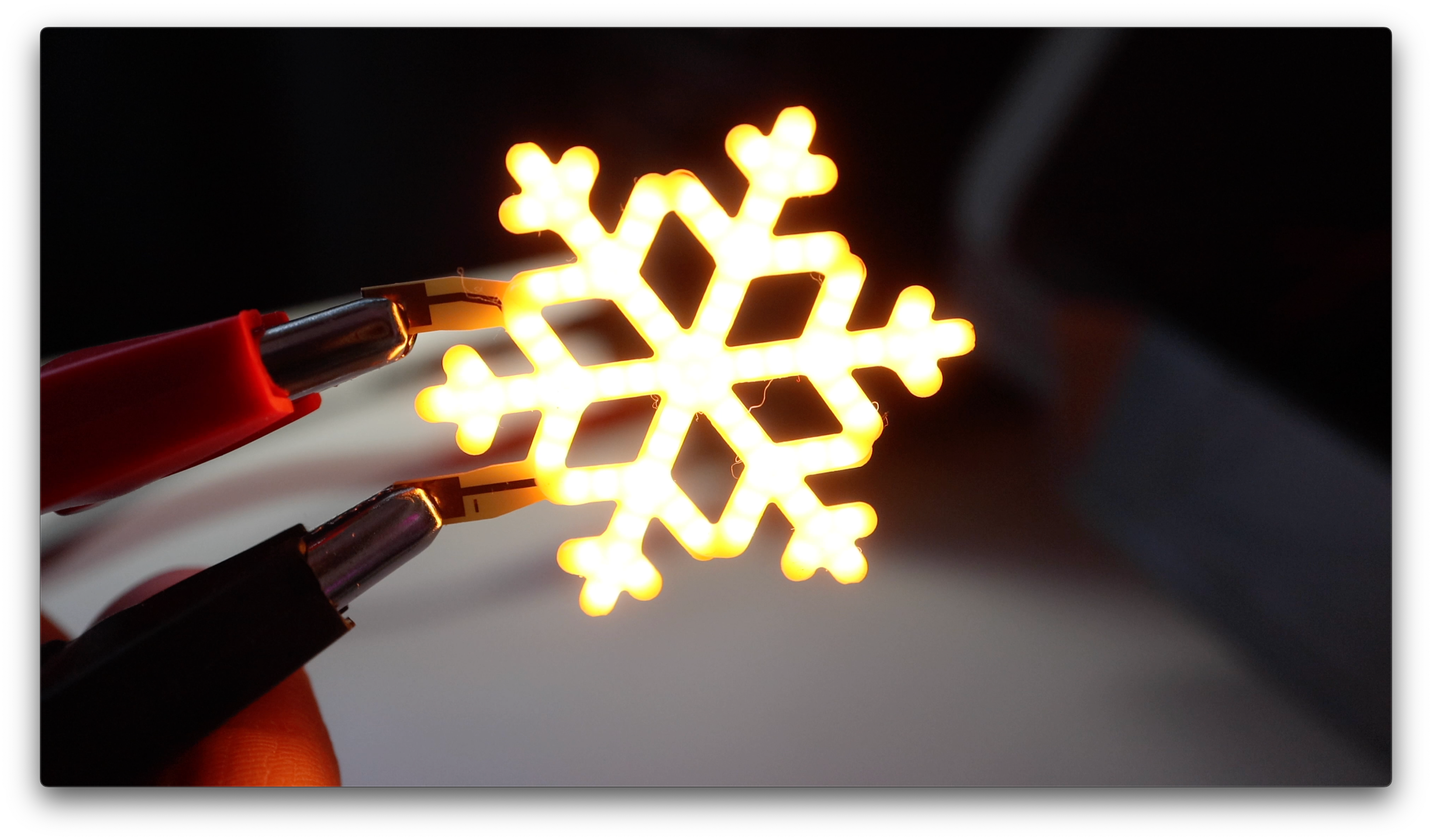
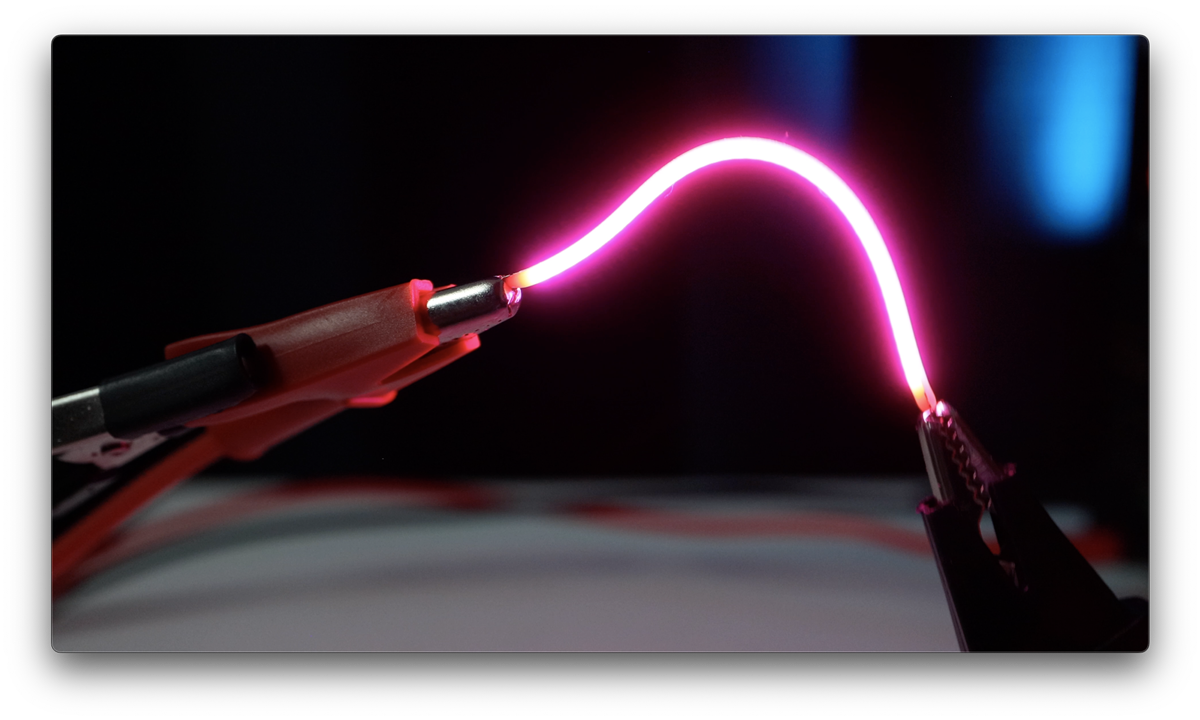
LED filament, sometimes called LED noodles by the maker community, look like glowing neon but are actually a dense row of micro LEDs bonded to a thin metal backing and coated in silicone. The diodes are packed so tightly together that they read as a continuous line of light rather than individual points. Most versions are flexible. The pack Natasha ordered was not, and that turned out to be the key property that made the design work.
"Most of these filaments are flexible but when I ordered the pack, that wasn't. That's when I realized that they could provide the structure to make my circuit sculpture design possible."
Rigid filaments can hold a position without support, which meant Natasha could use them as structural elements within the sculpture itself. The trade-off is that they are extremely brittle.
"The only downside to the rigid LED sticks is that they're extremely fragile. They don't bend, but they sure do break. The smallest amount of pressure just snaps them in half."
Electrically, the diodes within each stick are wired in parallel and run at 3V. Unresisted they can draw up to 200mA, so current limiting with a resistor is standard, with around 50mA being a sensible target for continuous use. The sticks Natasha used were 40mm in length. The positive terminal is conventionally identified by a small hole in the wire lead, though as she found out later, this is not consistent across all batches and manufacturers.
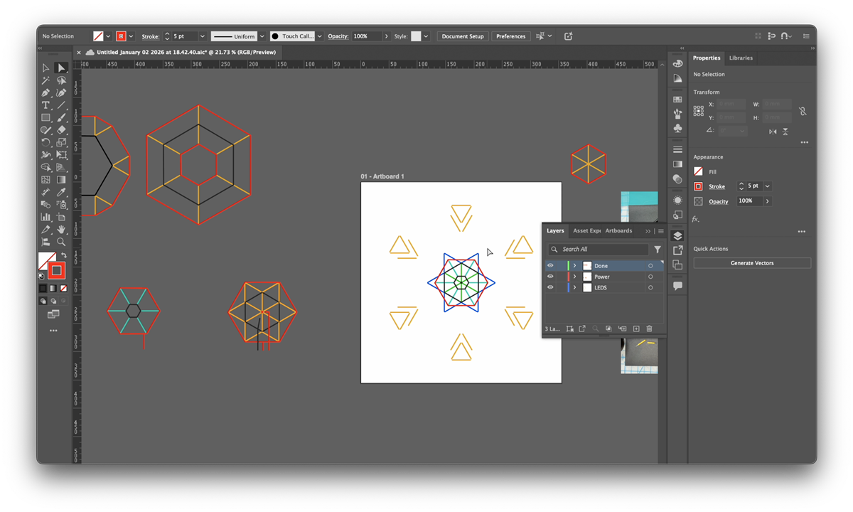
Planning the Circuit in Illustrator
The design groups the LED sticks into rings, with each ring having its own positive and negative rail so that each section can be controlled independently. To reduce the total amount of wire running through the sculpture, Natasha shared a common ground between adjacent pairs of rings.
"Instead of always having the negative side on the inside and the positive side on the outside, some of the pieces grouped two sections together so I had a ring of positive, a ring of negative with both groups attached, and a ring of positive again for the second group."
With the number of layers and connections involved, she moved the planning into Adobe Illustrator. She measured the 40mm LED sticks precisely (specifically the illuminated length rather than the full component length), placed a photo of her test layout on the canvas as a reference, and drew out the wire trace for each layer. Those diagrams then became the physical templates she printed and used to shape the copper wire against.
"This concept is super simple but when thinking in layers of LEDs this was a lot to think about. So to make sense of the layers of wire and wire traces I turned to Adobe Illustrator."
With all of the layers mapped out and printed, the plan was solid. She describes her mental state at this point as her brain feeling like jelly, so she committed to trusting the process and started building.
Shaping the Wire and Soldering the LEDs
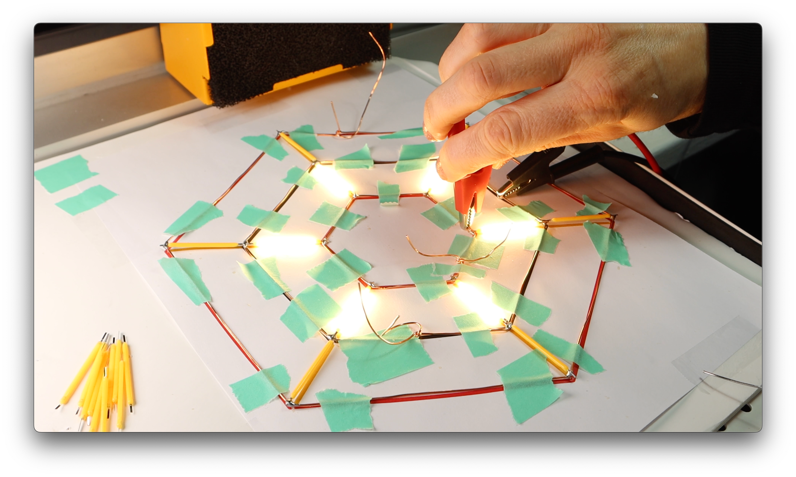
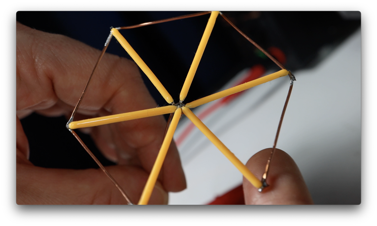
Natasha made a basic jig from foam board and map pins to hold the wire in position while she shaped it against her printed templates. The copper wire had enough spring to resist staying in place, so she ended up using a combination of the pins and tape to keep things set.
Each LED stick was placed onto the copper wire at the correct angle and tacked with a small amount of solder to hold it before moving on. Polarity has to be tracked throughout, which becomes harder as the build progresses.
"I knew that the side with the hole in it was positive but once you put solder on it you can't see the hole anymore, so that made it difficult to visually check that I had done it correctly."
Once solder covers the joint, the identifying hole is gone. The only way to verify polarity at that point is to test it electrically. Worth building that step into your process before starting rather than discovering it mid-build.
The other consistent problem was the fragility of the filaments once multiple LEDs were attached to the same layer. The copper wire traces are flexible, and that flexibility gets transferred to the LED sticks at their solder joints.
"Since the wire was flexible, the weakest link is the LED itself, so any little adjustment and the LED could pop. And it was really hard to not want to adjust the wire because if it bent a little bit you just think, oh I'll fix that real quick, and boom you snapped an LED."
Assembly: Layers, Magnets, and the Ground Bus
After the individual layers were done, Natasha paused for several days before attempting to assemble them. This is not presented as a failing; it is a good call.
"I was honestly terrified to put this together because each layer was so fragile, and it felt like the more pieces that I would connect together, the more risk I had of bending a wire and breaking the LEDs attached to it."
She used cube magnets as impromptu spacers to hold the layers at a consistent distance from each other while she worked on the ground connections. The ground wires were soldered in pairs first, then the pairs were joined into a single continuous ground bus that runs through the whole sculpture. Building it up in stages like this keeps each individual operation manageable.
For the base, she had a wooden block in her studio that she wanted to use. She connected all of the circuit wires to a piece of perfboard and screwed that to the top of the block. Perfboard here is working as an anchor and breakout panel for all of the individual positive leads, not as a conventional PCB. The unexpected outcome was that the copper wire structure was rigid enough to hold the entire sculpture upright on its own.
In total, four or five LED sticks broke during the whole build process. By her own estimate, that was fewer than she expected.

The Polarity Problem
When Natasha removed the first broken stick to replace it, she discovered that the second batch of LED filaments she had bought had the opposite polarity convention. The hole that marks the positive terminal on one manufacturer's product was on the negative terminal in this batch.
"I had just done this very tedious surgery to my circuit and it was perfectly soldered in place again, and it didn't work."
This is a known inconsistency with LED filament products. The hole-marks-positive convention is common but not universal, and it can vary between manufacturers and between production runs from the same supplier. The fix is simple: test any new batch for polarity before installing anything. A quick check with a known voltage and a current-limiting resistor takes seconds and avoids having to redo a completed joint.
Testing the Fade with Velostat
Before writing any code, Natasha wanted to see how the fading between groups would look in practice. She made a basic test rig using strips of conductive copper tape on a piece of foam to give her accessible contact points for each positive lead, then used a piece of Velostat as a hand-operated variable resistor.
Velostat is a carbon-impregnated polyolefin film with piezoresistive properties: its resistance drops as you apply pressure to it. A small piece sandwiched between two conductive surfaces shifts from several kilohms at rest down to around one kilohm under firm pressure. By pressing harder or lighter on the Velostat against the contact points, she was able to vary the brightness of each LED group continuously, and move between groups by shifting where she applied pressure.
"I'm pressing and you can see I'm lightening up, I'm pressing down harder, and then I can move over to press a different wire. So there's different connection levels, and I think that's gonna look so cool."
As a quick way to validate the animation concept before committing to any software, it works well. No microcontroller, no code, just a useful material property doing the job of a PWM signal by hand.
What She Would Do Differently and What Comes Next
Natasha wraps up with three specific things she would change if she were starting again.
Wire gauge for the structural runs. The fine copper wire she used for the traces within the snowflake is the right choice aesthetically because it visually disappears and lets the LED filaments stand out. But using the same wire gauge for the longer vertical runs down to the base means the sculpture moves around more than she would like. Her fix would be to use heavier wire only for those support runs, keeping the finer wire for the circuit traces themselves.
Solder quality. She was careful about her solder joints early in the build but relaxed her standards as the volume of joints mounted up. For a first build doing this many LEDs she decided that was an acceptable trade-off, but for future projects she would be more precise, particularly if the solder joints are as visible as they are in circuit sculpture.
LED orientation. This one is subtle but worth knowing. The LED filament sticks have a front face. The silicone coating wraps the whole component, but the LEDs inside emit noticeably more light in one direction than the other. During initial installation Natasha was careful to orient each stick face-forward. During repairs, working on a nearly-complete fragile sculpture, she was less consistent.
"There are a few LEDs that are just a hair dimmer when looking at the sculpture because they're facing backwards."
Polarity and face orientation are both worth tracking every time a stick is installed or replaced. The hole tells you which way the current flows. The face tells you which way the light goes.
The sculpture has all of its individual positive leads accessible through the perfboard base, ready to be driven by PWM-capable outputs from a microcontroller. The ground bus is unified. The mechanical build is done. The question Natasha is working through is what to make it do.
Options she is considering include a VU meter that responds to audio amplitude, a data visualiser, a weather-reactive mode that triggers when it actually snows, or a purely musical version that breathes and twinkles in sync with a wintery soundscape. The Velostat test already showed the fade behaviour looks exactly as intended, so the foundation is solid.
"What if it went off when it actually snowed? Or if I just make it something that's musically beautiful. So if I put on some wintery soundscape, does it twinkle and breathe with the music?"
The next time Natasha approaches this project on element14 presents, it will cover the microcontroller side and how the animation comes together. You can contribute by suggesting in the comments below on what direction Natasha can take the project.
Planned Bill of Materials
| Product Name | Manufacturer | Quantity | Buy Kit |
|---|---|---|---|
| Micro:bit SBC, BBC MICRO:BIT SINGLE, V2.21, nRF52833 | micro:bit | 1 | Buy Now |
Additional Parts
| Product Name | Manufacturer | Quantity |
|---|---|---|
| LED Filaments | Pretyzoom | 1 |
| 20 Guage Copper Wire | 1 | |
| Small LED Snowflake | anso | 1 |
| Perf Board | Radio Shack RIP :( | 1 |
-

beacon_dave
-
Cancel
-
Vote Up
0
Vote Down
-
-
Sign in to reply
-
More
-
Cancel
-

beacon_dave
in reply to beacon_dave
-
Cancel
-
Vote Up
0
Vote Down
-
-
Sign in to reply
-
More
-
Cancel
-

TechnoChic
in reply to beacon_dave
-
Cancel
-
Vote Up
0
Vote Down
-
-
Sign in to reply
-
More
-
Cancel
Comment-

TechnoChic
in reply to beacon_dave
-
Cancel
-
Vote Up
0
Vote Down
-
-
Sign in to reply
-
More
-
Cancel
Children