

Watch Clem Pocket the Industrialisation
Clem has always had a healthy suspicion of expensive industrial hardware. Looking at the price of programmable logic controllers (PLCs), his initial reaction was much the same as many makers staring at a catalogue of industrial equipment: surely there cannot be that much inside a PLC to justify the cost.
Rather than speculate, he decided to build one.
The result is a PocketBeagle 2 based PLC project that starts out as a straightforward maker build and gradually evolves into something much closer to a genuine industrial controller. Along the way, it becomes a lesson in electrical isolation, PCB layout, device tree configuration, realtime processing and the countless small decisions that separate a prototype from a product.
As Clem puts it:
"Sometimes they are actually just an Arduino in a fancy box and some relays... but there are also legacy systems with big brand names and high price tags and these are built for reliability."
His goal was not to reproduce an industrial PLC exactly, but to understand where all that engineering effort goes.
Starting with an Open PLC Platform
Commercial PLCs often come with proprietary software ecosystems, vendor lock-in and long-term support guarantees. Clem wanted to approach the problem from a different direction.
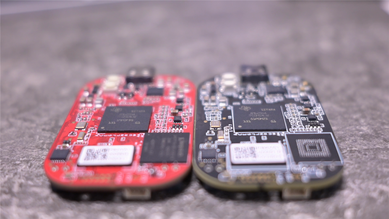
Instead of using a dedicated PLC platform, he based his design around the PocketBeagle 2, a compact Linux-capable development board built around Texas Instruments' AM6254 Sitara processor.
What attracted him was the combination of high-level Linux functionality and low-level deterministic control.
"I wanted it to have serious capabilities. It should have realtime Linux support and it also should have a deterministic way of controlling the inputs and outputs."
Unlike many maker boards, the PocketBeagle 2 includes two Programmable Realtime Units (PRUs), effectively dedicated microcontroller-class cores integrated into the processor.
These can operate independently from Linux and are designed specifically for tasks that require predictable timing.
"We have the Linux controls around USB devices, high-level stuff like AI models and communication with networks and other devices, and then the PRUs can control all the inputs and outputs."
The AM6254 architecture immediately begins to resemble the split architecture found in many industrial systems. Linux handles networking, storage and complex applications while dedicated realtime processors handle machine control.
Clem even points out that the second PRU could act as a watchdog, redundancy controller or cross-checking processor, similar to techniques found in safety-oriented industrial equipment.
Version One: The Maker Approach
The first PLC design intentionally follows the path many hobbyists would take.
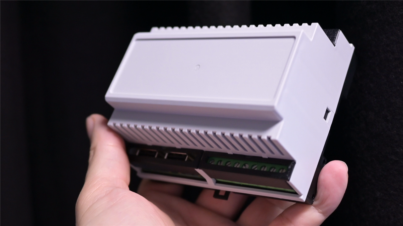
A Hammond DIN rail enclosure serves as the mechanical foundation, while a relatively simple two-layer PCB carries the electronics. The board includes:
- PocketBeagle 2 controller
- Microchip USB2514 USB 2.0 hub controller
- Four analogue input channels
- Four relay outputs
- ULN2003 Darlington relay driver
- Dual USB host ports
- DIN rail mounting format
The PCB itself was designed quickly.
"I eyeballed the position of all the connectors and I tried to put as many features in here as possible."
Rather than spending days optimising every mechanical detail, the focus was on getting something functional into the enclosure as quickly as possible.
One feature Clem was especially keen to exploit was the PocketBeagle 2's integrated twelve-bit ADC. Unlike a typical Raspberry Pi, analogue inputs can be connected directly to the processor without requiring additional converter hardware.
The analogue channels are exposed through simple screw terminals, providing an easy way to interact with sensors and control inputs. The USB subsystem was another area where the project deliberately pushed the platform. By integrating the USB2514 hub controller, the PLC gains multiple USB ports for cameras, storage devices and peripherals.
On paper, it looked remarkably capable. Unfortunately, industrial design concerns do not appear on a schematic until something goes wrong.
When "Works" Isn't Good Enough
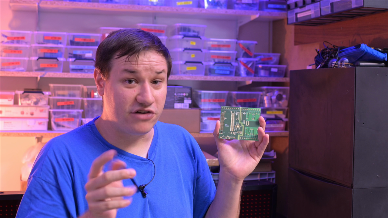
The first design functions. For many projects, that would be a success.
For a PLC, however, functionality is only the starting point.
Clem soon began identifying weaknesses that would become serious problems in an industrial environment.
The first issue was electrical safety.
"There is no real isolation in the original design. In case something goes wrong there could potentially be 230 volts everywhere in the system."
The relay outputs are capable of switching mains-voltage loads, yet the control electronics existed dangerously close to circuitry carrying higher voltages.
Industrial equipment depends heavily on segregation between control electronics and power electronics. Without that separation, failures can have consequences far beyond a damaged PCB.
The USB implementation also lacked many of the protections expected in a commercial design.
The original version provided only the minimum necessary circuitry to make the USB hub operate.
There was:
- No ESD protection
- No overcurrent protection
- No controlled fault response
- No dedicated USB power monitoring
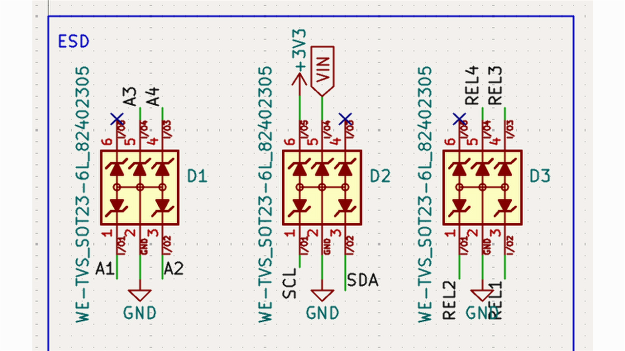
These omissions are common in maker projects because they are often invisible during normal operation. Industrial equipment, by contrast, must survive repeated abuse from the outside world.
Analogue routing presented another problem.
"I've routed my analogue ports right next to the relays. That will not work very good because they will couple into it."
Relay switching generates electrical noise. Placing sensitive ADC signals next to relay circuits creates opportunities for incorrect readings, instability and potentially damage.
These are exactly the sort of layout considerations that are easy to overlook when the first goal is simply getting a board manufactured.
Building a More Professional Controller
The second board revision demonstrates how quickly extra engineering effort accumulates.
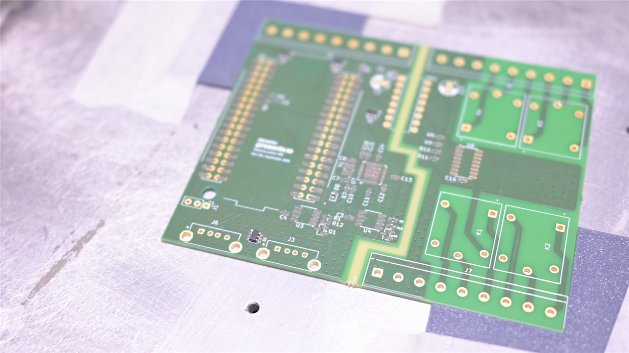
Clem moved to a four-layer PCB, improved component selection, reworked the enclosure integration and fundamentally redesigned the relay section.
More importantly, he stopped trying to maximise feature count and instead prioritised reliability.
"I preferred having good layout instead of more features on there because that is what the professional world considers the most important bit. Safe and reliable operation."
The revised USB implementation became significantly more sophisticated.
Dedicated current-limiting circuitry and fault detection were added to protect both connected peripherals and the PLC itself.
"These have current control chips specifically ordered and they have to detect if something goes wrong so your device that you plug into these USB ports can't destroy the overall thing."
This redesign required additional board area, forcing the reduction from four easily accessible USB ports down to two.
That trade-off between capability and robustness appears repeatedly throughout industrial design.
Isolation the Right Way
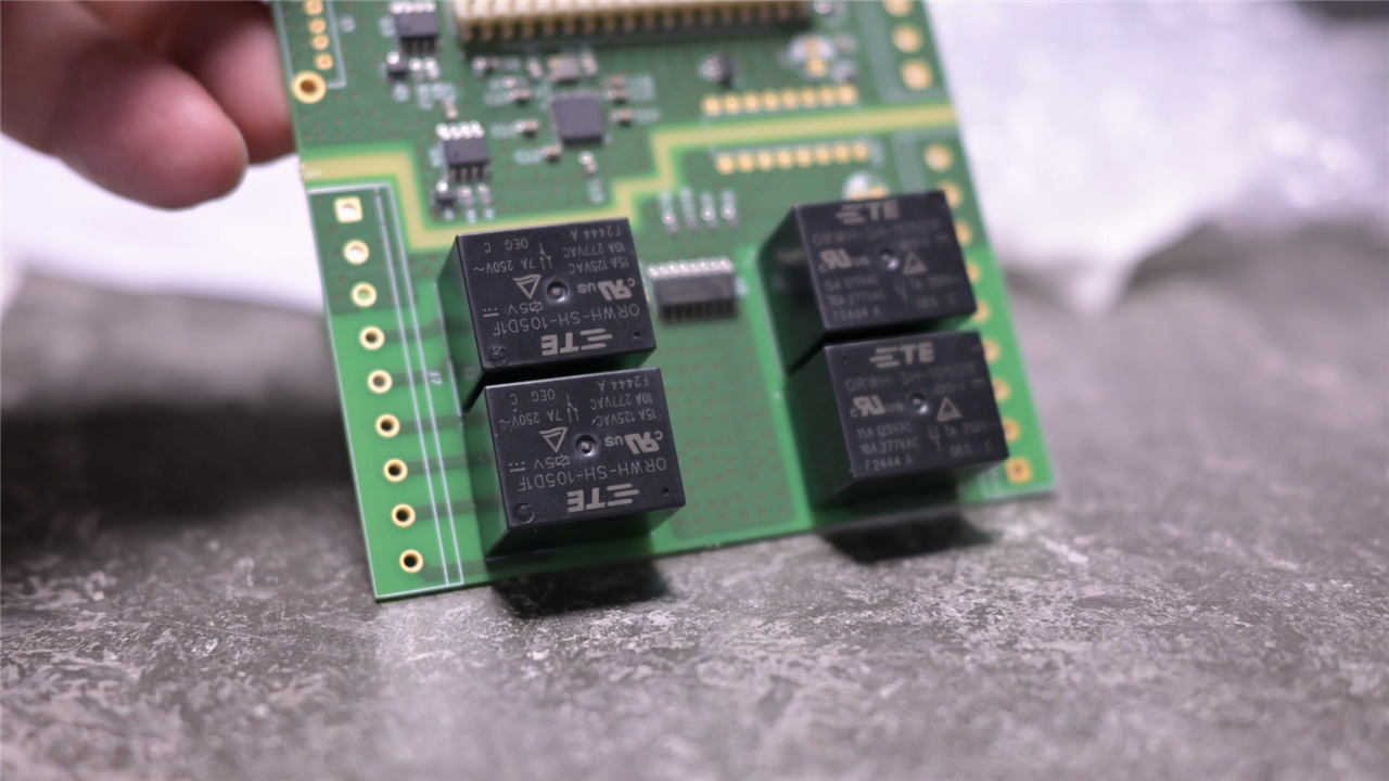
The most dramatic change involved the relay outputs. The revised PCB treats the relay circuitry and logic circuitry almost as completely separate systems. A dedicated isolation boundary divides the board into two sections. The only intentional signal path crossing that boundary is an optocoupler.
"An optocoupler is a way of galvanic isolation meaning there is no actual direct connection between these two halves. It is just and only a connection by light."
The relay control signals pass through an optocoupler before driving the ULN2003 relay driver.
This ensures that electrical disturbances from the relay side cannot directly propagate into the processor circuitry.
Even power supplies were separated.
Two isolated DIN rail power supplies were used: one dedicated to logic electronics and another for relay operation.
"We're truly isolated."
The resulting architecture begins to resemble industrial control hardware far more closely than the original all-in-one design.
The Device Tree Learning Curve
One of the most educational aspects of the project came from the software side.
Developers accustomed to Arduino or Raspberry Pi ecosystems often expect GPIO pins to work immediately.
The PocketBeagle 2 takes a more embedded Linux approach.
GPIO functionality must first be defined through device tree overlays.
"The apparently simple job of making a GPIO output starts involving device trees, pin multiplexing and the details of the underlying SoC."
Because the AM6254 allows pins to serve multiple functions, Linux must be explicitly told how they are being used.
Clem candidly describes the experience:
"Device tree overlays are very intimidating and complicated and I don't even halfway know what I actually did there."
Once configured correctly, however, the flexibility becomes apparent. Linux gains direct access to GPIO, ADC resources and other processor features while still allowing PRU-based realtime control.
That flexibility is one of the PocketBeagle 2's greatest strengths, but it comes with a significantly steeper learning curve than many maker platforms.

Working with the Onboard ADC
The analogue subsystem proved much more straightforward.
Clem exposed four ADC channels and demonstrated how Linux can read them directly through the Industrial I/O framework.
The Python implementation is refreshingly simple.
ADC_PATH = "/sys/bus/iio/devices/iio:device0"
VREF = 1.8
ADC_MAX = 4095

return (raw / ADC_MAX) * VREF
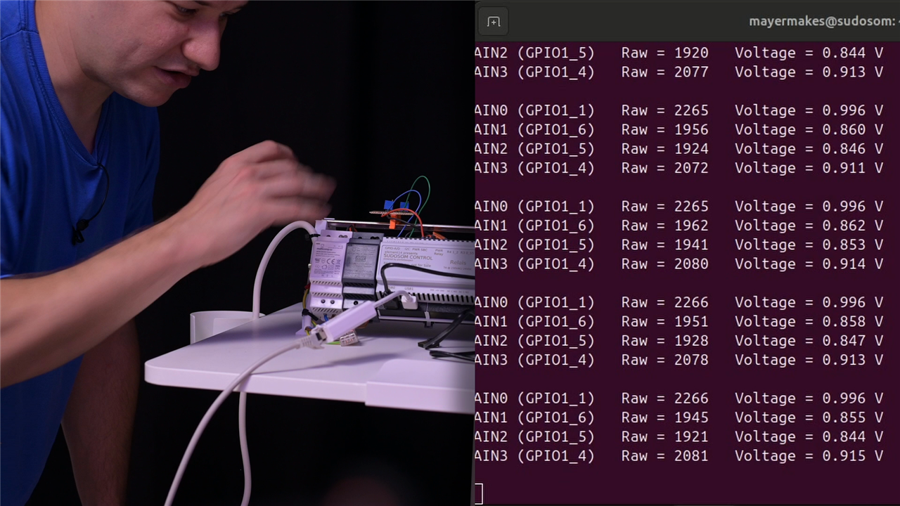
Raw readings are collected from Linux system files and converted into voltages using the 12-bit ADC range. The implementation continuously reads all four channels and reports both raw counts and calculated voltages.
This direct ADC access became a key part of the final demonstration.
A Useful Failure
Unfortunately, not everything worked perfectly.
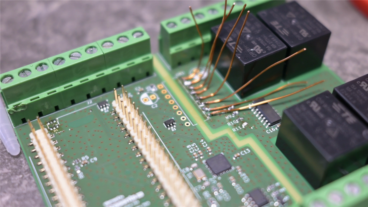
One of the relay isolation circuits exposed a design mistake.
The optocouplers were treated like standard logic devices rather than LED-driven isolation components.
Current-limiting resistors had been omitted.
"With a 3.3 volt logic level I should have used a 330 ohm resistor."
The result was that the optocoupler LEDs never switched fully off once activated.
"Once the LED activates for the first time it sits there drawing current at about two volts and never deactivates again."
The relays therefore refused to operate correctly during the final demonstration.
Rather than hide the mistake, Clem used it to illustrate a reality of professional hardware development: unfamiliar parts frequently behave differently from assumptions made during schematic capture.
Testing, redesign and verification are fundamental parts of the engineering process.
Live Colour Detection Demo
For the final demonstration, the PLC uses its analogue inputs, USB subsystem, Linux environment and networking stack simultaneously.
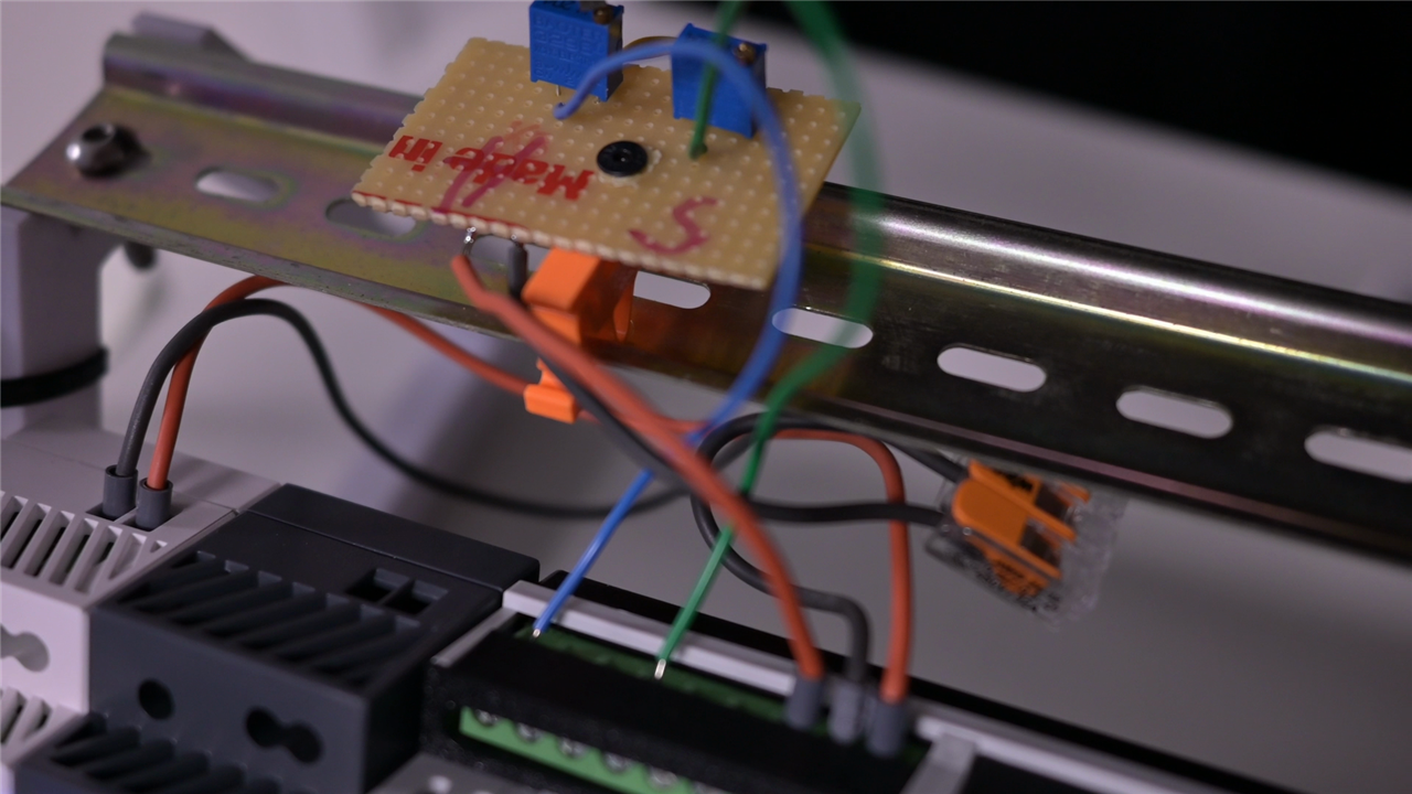
A USB webcam streams video into OpenCV while two analogue channels control detection parameters.
One analogue input selects the target hue while another sets the intensity threshold.
The software converts ADC values into colour detection parameters in realtime.
application_hue = int(
    (raw / ADC_MAX) * 255
)

opencv_hue = int(
    (application_hue / 255) * 179
)
A value of 150 corresponds approximately to blue, allowing trim potentiometers wired to the PLC to tune colour detection while the system is operating.
The software analyses webcam imagery, performs HSV filtering, calculates contour sizes and overlays detection results on the live image.
Results are then streamed over the network using a built-in web server.
During testing, Clem adjusted the analogue inputs live while watching colour detection track the blue colour of his shirt.
"We can set the hue and the saturation with these analogue potentiometers on the fly and observe the stream over the network."
The demonstration neatly combines nearly every subsystem available on the PLC.
So Why Are PLCs So Expensive?
By the end of the project, Clem's original question had evolved considerably. The first board genuinely supports the argument that many PLCs appear to be little more than a processor, some I/O and a box.
The second board reveals the hidden engineering. Isolation barriers. ESD protection. Current limiting. Optocouplers. Power integrity. Analogue layout. Device tree configuration. Mechanical integration. Realtime processing. Redundancy. Testing. Verification.
None of these individually seem particularly dramatic. Together they account for a substantial amount of engineering effort.
"Now that we know how incredibly difficult it is to make a real PLC, a system that has redundancy, safety, watchdogs and all these constructive features to make the relays safe and all the connections and inputs reliable, I think we can appreciate that sometimes they just have to cost more."
That does not mean every industrial PLC automatically represents good value. It does demonstrate that the real complexity often lies in the details that nobody notices until they are missing. Clem set out to build a PLC to understand where the money goes. What he discovered is that making something look like a PLC is relatively easy.
Building something that begins to behave like a professional industrial controller is a completely different challenge.
Supporting Files and Links
- PocketBeagle 2 Documentation
- Device Tree Tutorial by Grippy98
Bill of Materials
| Product Name | Manufacturer | Quantity | Buy Kit |
|---|---|---|---|
| Optocoupler, Darlington Output, 4 Channel, DIP, 16 Pins, 50 mA, 5.3 kV, 500 % | ISOCOM | 1 | Buy Now |
| USB Connector, USB Type A, USB 2.0, Receptacle, 4 Ways, Through Hole Mount, Vertical | multicomp | 2 | Buy Now |
| Wire-To-Board Terminal Block, 5.08 mm, 3 Ways, 30 AWG, 12 AWG, 3.31 mm², Screw | würth | 9 | Buy Now |
| Plastic Enclosure, DIN Rail, Polycarbonate, 90 mm, 105 mm, 58 mm, IP20 | Hammond | 1 | Buy Now |
| Pin Header, Board-to-Board, 2.54 mm, 2 Rows, 40 Contacts, Surface Mount | Multicomp pro | 2 | Buy Now |
| Development Kit, PocketBeagle 2, AM6254, ARM Cortex-A53 / Cortex-M4F | beagleboard | 1 | Buy Now |
| Flash Memory Card, MicroSDHC Card, 16 GB, Class 10, UHS-I U1, A1 | integral | 1 | Buy Now |
| DARLINGTON TRANSISTOR ARRAY, SOIC-16 | onsemi | 1 | Buy Now |
| General Purpose Relay, ORWH Series, Power, Non Latching, SPDT, 5 VDC, 10 A | TE | 4 | Buy Now |
| AC/DC DIN Rail Power Supply (PSU), ITE, 1 Output, 15 W, 5 VDC, 3 A | meanwell | 1 | Buy Now |
| AC/DC DIN Rail Power Supply (PSU), ITE, Industrial & Household, 1 Output, 15 W, 5 VDC, 3 A | multicomp pro | 1 | Buy Now |
| USB Interface, USB Hub Controller, USB 2.0, 3 V, 3.6 V, QFN, 36 Pins | microchip | 1 | Buy Now |
| ETHERNET ADAPTER, USB3.0 GIGABIT WHI | 1 | Buy Now | |
| DIN Mounting Rail, DIN Mounting Rail, Racks & Cabinets, 1 m, 7.5 mm, 35 mm, Steel | 1 | Buy Now | |
| TVS Diode, WE-TVS, Unidirectional, 5 V, 6.8 V, SOT-23, 6 Pins | würth | 4 | Buy Now |
| MIC2025 | Microchip | 2 | MIC2025 |
Additional Parts
| Product Name | Manufacturer | Quantity |
|---|---|---|
| Crystal and caps for the usb2514→ 24MHz | ||
| usb current control ICs + mosfets |
Top Comments