

Rather than wait weeks to borrow a thermal imaging camera, Katie Dumont set out to build one from scratch. Combining a Seeed Studio MLX90640 thermal array sensor with an Arduino UNO R4 Minima and a colour display, she produced a portable thermal camera that can highlight heat loss, reveal hidden hot spots and display temperature variations in real time. The project goes beyond simply wiring modules together, with a custom-designed 3D printed enclosure, rugged physical controls, configurable temperature scales and plenty of experimentation to get the best image from the sensor. It's a practical build that demonstrates just how accessible thermal imaging has become for makers, engineers and anyone curious about what's really going on beneath the surface.
Get Fired Up and Watch Katie Build
Why wait to borrow a thermal imaging camera when the core technology is now available as a relatively affordable sensor module? Faced with long waiting lists for energy-efficiency thermal cameras, Katie Dumont decided to build one instead. The result is a handheld thermal imaging camera based around an Arduino UNO R4 Minima, combining a 32 × 24 infrared sensor array with a colour touchscreen display, physical controls and a custom-designed enclosure.
Rather than replicating the behaviour of a commercial thermal camera, the project explores how easily a thermal imaging system can be tailored to specific requirements. Temperature ranges can be adjusted, colour mappings can be customised and the hardware remains open to future upgrades.

The Hardware Platform
At the heart of the build is the Seeed Studio MLX90640 infrared thermal imaging sensor. Unlike a conventional camera, the MLX90640 does not capture visible light. Instead, it measures infrared radiation across a grid of 768 sensing elements arranged in a 32 × 24 array.
"It's got an array of thermal sensors of 32 by 24 of them so should get a fairly decent image of the temperatures."
The sensor communicates over I²C, making it straightforward to interface with modern microcontroller platforms. One of the aspects that immediately stood out during development was its quoted accuracy.
"It's plus and minus 1.5 degrees C accuracy so I should be fairly confident with what I get out of this as an accurate representation of the temperature."
Supporting the sensor is the Arduino UNO R4 Minima, based on the Renesas RA4M1 microcontroller. With significantly more RAM and processing capability than earlier Uno generations, it is capable of handling the calculations required to process MLX90640 image data while simultaneously driving a display.
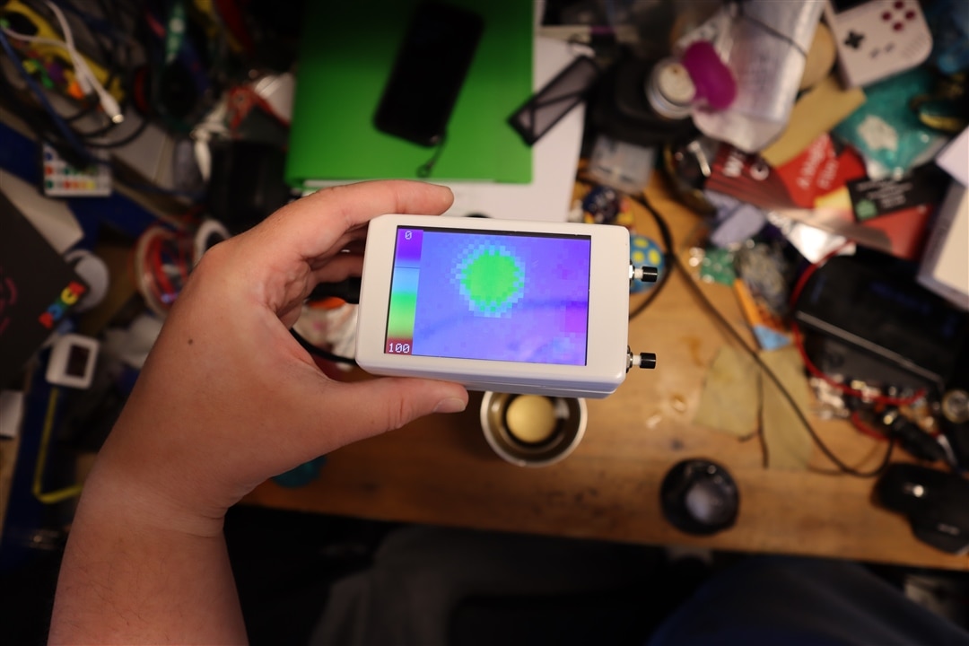
Visual output is provided by a DFRobot Fermion capacitive touchscreen display module, creating a compact self-contained handheld instrument. Two Multicomp Pro pushbuttons provide range adjustment controls, while a custom 3D-printed enclosure holds everything together.
Validating the Sensor and Designing for Real-World Use
Before committing to the enclosure design and software architecture, the project began with a simple proof-of-concept test.
The thermal sensor and display were wired together with the Arduino, and example software from the display and sensor libraries was adapted into a quick prototype. To verify operation, two everyday thermal references were selected: an ice cube and a container of near-boiling water.
"I've taken the example code for the library for the camera and the screen and just popped them together just to make a really simple test to check this is going to do what I want it to do."
The resulting thermal images immediately demonstrated that the system was operating correctly. Cold regions appeared deep blue, while high-temperature regions saturated towards red. Even subtle thermal effects became visible.
"I'm getting detail of the steam coming off the cup as that greeny, so not as hot but hotter than ambient temperature."
The testing phase also verified that temperature gradients around the cup could be observed clearly, with transitions through yellow and green before reaching ambient background temperatures. Many DIY thermal imaging projects stop at a bench-top prototype, but this build was intended to become a practical tool capable of being stored in a toolbox and used repeatedly.
Although the display includes touch capability, a conscious decision was made not to use touchscreen controls for normal operation.
"I also want quite a rugged tool that I can keep in a toolkit."
Instead of relying on touch gestures, the design uses dedicated physical buttons to adjust display ranges. This approach allows a protective acrylic window to be fitted over the display, increasing durability while simplifying operation.
"For just two buttons, two physical buttons are going to be much stronger in a work environment than having a touch screen."
It is a practical engineering compromise. While touchscreens provide flexibility, robustness frequently takes priority when creating equipment that may be transported regularly or used in harsher environments.
Software Architecture
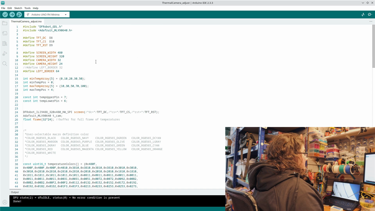
The firmware was developed using the Arduino IDE, combining display libraries from DFRobot with thermal imaging support from the Adafruit MLX90640 library.
Rather than relying on a fixed colour scale, the software introduces configurable temperature limits and colour mappings. Arrays define selectable temperature bands and associated palette values, allowing the display range to be adapted to different inspection scenarios.
"I've made an array of temperatures that I think would be nice to choose between for the minimum and for the maximum."
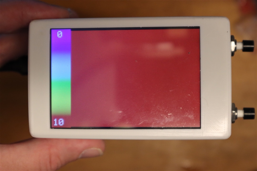
A significant enhancement beyond the initial proof-of-concept was the addition of a graphical reference scale. Alongside the thermal image itself, the software generates a colour bar displaying the current temperature mapping and ambient reference point.
"I've made a little bar on the screen just so you've got something to reference."
This is particularly useful when comparing thermal scenes because colours alone can sometimes be misleading without context. Showing the active scale ensures that temperature differences remain meaningful as users adjust ranges.
The display rendering process converts each measured temperature into a colour lookup value and then expands the low-resolution thermal array into larger screen pixels.
"Displaying each pixel as 13 by 13 square."
This scaling approach preserves the sensor's underlying structure while making the image large enough to be useful on the handheld display.
Custom Enclosure Development and Performance and Practical Applications
To transform the electronics into a finished product, a dedicated enclosure was modelled and 3D printed.
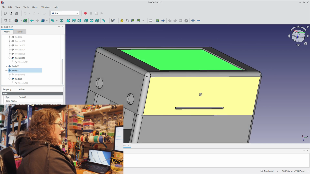
The housing was designed around the precise requirements of the hardware, including mounting locations for the Arduino, openings for the pushbuttons, accommodation for the acrylic display cover and a dedicated aperture for the thermal imaging sensor.
The enclosure design was created in FreeCAD, allowing dimensions to be adjusted until everything aligned correctly. Once printed, the finished parts closely matched the original CAD model and provided the foundation for final assembly.
The completed unit feels much closer to a commercial inspection tool than a development-board prototype, while still retaining all of the flexibility of an open-source design. The finished camera provides a useful way of visualising heat loss, identifying hot components and locating unexpected temperature variations. Like many MLX90640-based systems, it operates at relatively modest frame rates due to the amount of processing required to convert raw sensor data into temperatures and rendered images.
Even so, the camera is perfectly capable of highlighting thermal differences across surfaces, electrical equipment and household environments.
"It'll give me an idea of just what temperature something is with a visual graphic of where that is."
For energy-efficiency surveys, that means doors, windows, insulation gaps and draught-prone areas become immediately visible. For electronics work, it offers a way to identify unexpectedly hot components and thermal bottlenecks without specialised commercial equipment.
Future Enhancements and Final Thoughts
One of the advantages of building a thermal camera rather than purchasing a finished product is that new capabilities can be added whenever the hardware allows.
The most obvious next feature would be image capture.
"The addition for actually capturing that picture and having it as an image file."
The display hardware already includes an SD card slot, opening up the possibility of storing thermal snapshots directly to removable media. However, implementing this feature requires careful consideration.
"The only thing I'd worry about is in processing that it might make the whole camera image speed that it's updating slower."
Another particularly interesting possibility would be combining visible-light imagery with thermal information, similar to the image-overlay functionality found on professional thermal cameras.
"To have an actual normal camera and be able to overlay the thermal imaging sensor data onto a real picture."
While technically achievable, this would likely demand considerably more processing power than is available within the current hardware configuration. The concept nevertheless demonstrates how extensible the design could become should a future revision migrate to a more powerful platform. This project demonstrates just how accessible thermal imaging technology has become. By combining an MLX90640 infrared sensor, an Arduino UNO R4 Minima, a colour display and a carefully considered enclosure design, Katie has produced a capable handheld thermal camera that can be customised far beyond the capabilities of many entry-level commercial units.
What began as an attempt to avoid a lengthy borrowing queue evolved into a fully featured thermal inspection tool with configurable temperature ranges, physical controls, a rugged enclosure and a clear upgrade path. Whether used for identifying household heat loss, examining electronic assemblies or simply exploring temperature differences in the world around it, it is an excellent example of turning readily available maker hardware into a genuinely useful instrument.
Key Hardware Used
- Arduino UNO R4 Minima Development Board
- Seeed Studio MLX90640 Thermal Imaging Sensor (32 × 24 IR array)
- DFRobot Fermion TFT Capacitive Touch Display
- Multicomp Pro Pushbutton Switches
- 3D-printed PLA enclosure
- 3 mm acrylic display protection window
Interested in building your own version or adapting the design?
Supporting Links, ECAD and Code
-
Parts Used and Buy Links
| Product Name | Manufacturer | Quantity | Buy Kit |
|---|---|---|---|
| ABX00080 Development Board, UNO R4 Minima | Arduino | 1 | Buy Now |
| DFROBOT Capacitive TouchScreen, Fermion, TFT LCD, Arduino Board | DFROBOT | 1 | Buy Now |
| 114020141 Thermal Imaging Camera/IR Array Board | SEEED Studio | 1 | Buy Now |
| R13-24A-05-BB Pushbutton Switch, R13-24, 7.2 mm, SPST-NO" | Multicomp Pro | 2 | Buy Now |
| MP015138 3D Printer Filament, 1.75mm, Milk White, PLA" | Multicomp Pro | 1 | Buy Now |
| Product Name | |||
| 3mm Clear Acrylic sheet | |||
Top Comments