

Let Pat spin you Right Round
Imagine spinning a shaft several turns while an entire system is completely powered down, applying power again, and instantly recovering the exact position. No battery backup. No homing routine. No absolute encoder battery to maintain. Just an immediate and accurate position report.
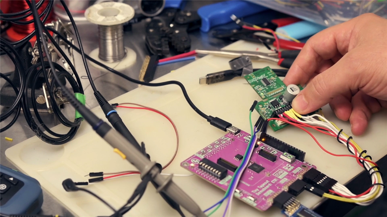
That is exactly what was demonstrated using the Analog Devices ADMT4000, a magnetic multiturn position sensor capable of tracking both angle and revolution count even while unpowered. To put the device through its paces, the sensor was connected to an RP2350-based Tiny Tapeout demo board running MicroPython, combined with an SSD1306 OLED display and a ballscrew-driven positioning setup.
"It's easy enough to measure the angle on wake, but how does a sensor count complete revolutions with no battery backup? Zero power."
That question sits at the heart of what makes the ADMT4000 such an unusual device.
Why Multiturn Position Tracking Matters and A Look at the ADMT4000 Hardware
Many positioning systems can measure angular displacement while powered, but maintaining accurate position information across power cycles is a different challenge altogether. Systems such as CNC equipment, automated positioning stages, robotic actuators, steering systems and battery-powered industrial instruments often rely on homing procedures after power-up.
Those routines consume time, energy and mechanical life. In applications where equipment may remain switched off for extended periods and then be expected to report its position instantly, traditional approaches become inconvenient or outright impractical.
The demonstration centred on a linear positioning table driven by a ballscrew with a pitch of 5 mm per rotation. A battery-powered deployment was envisioned where equipment could spend most of its life sleeping, yet still wake up and immediately know its location regardless of movement while power was removed.
"No power, but no homing sequence and no constant recalibrating. Just always works, reporting position the instant it's turned on."
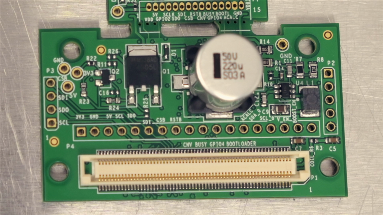
The ADMT4000 evaluation kit consists of two board sections. The upper section contains the sensor itself and can be detached from the main evaluation platform, while the lower section provides development and support circuitry.
According to Analog Devices' specifications, the device supports:
- True power-on multiturn sensing
- Tracking up to 46 complete turns
- ±0.25° angular accuracy
- Up to 100 kSPS update rates
- SPI communications
- 16 mT to 31 mT magnetic operating range
- Integrated diagnostic and temperature monitoring features
The sensor uses a paired magnet and magnetic shield assembly. During testing, the supplied ADMAGB3476 magnetic assembly was coupled directly to a ballscrew through a custom printed adapter.
Field strength and alignment proved more important than expected. Measurements with a gauss meter showed that while the magnet produces well over 100 mT close to its surface, the field drops rapidly at typical operating distances.
"The sensor wants between 16 and 31 millitesla."
This narrow operating window explains the emphasis Analog Devices places on mechanical positioning and alignment throughout the evaluation documentation.
The Physics Behind the Magic
The most fascinating part of the project was the investigation into how the ADMT4000 achieves its true power-on behaviour.
In reality, the package contains three magnetic sensing technologies working together. The absolute angle measurement is performed using anisotropic magnetoresistance (AMR), while the power-off turn counting relies on giant magnetoresistance (GMR).
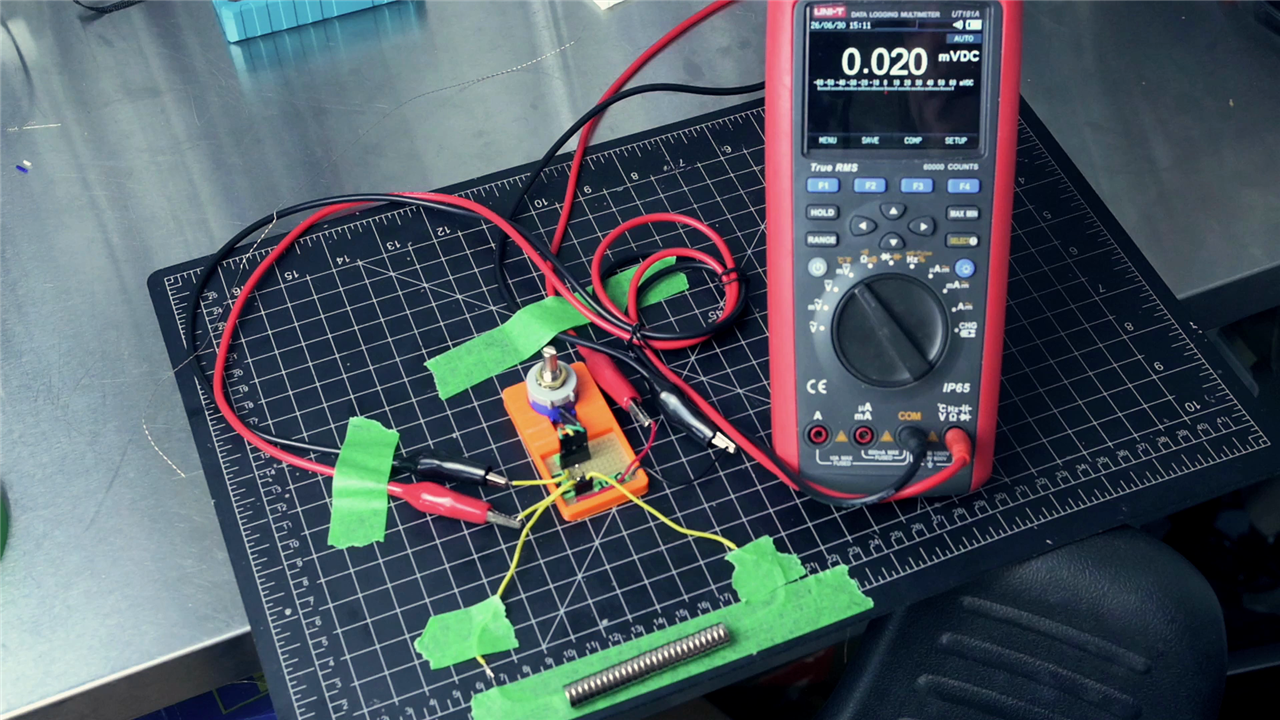
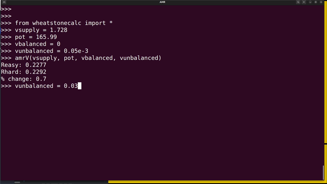
To better understand AMR, an experiment was created using a section of nickel-based guitar string, a Wheatstone bridge circuit and a collection of strong magnets.
The setup attempted to observe the tiny changes in resistance that occur when magnetic fields alter electron scattering inside ferromagnetic materials.
"We're demonstrating AMR, a quantum effect, in this little piece of guitar string with just a regular DMM."
The measured change was estimated at approximately 0.4%, corresponding to only a fraction of a micro-ohm. Despite the extremely small magnitude, the Wheatstone bridge arrangement successfully revealed the effect.
This experiment provides an accessible demonstration of the same physical phenomenon the ADMT4000 exploits to determine angular position.
From AMR to GMR
While AMR provides angle information, it cannot explain how position survives complete loss of power.
That capability comes from GMR structures fabricated as microscopic magnetic nanowires inside the device.
Rather than storing information electronically, the ADMT4000 physically records rotational history through the movement of magnetic domain walls along a spiral-shaped structure. The resulting magnetic state remains present whether power is applied or not.
"When power is applied, the chip simply reads the resistance state of the spiral and knows the accumulated turn count."
This physical storage mechanism explains the sensor's unusual 46-turn range. The internal spiral can only accommodate a finite number of magnetic state transitions, resulting in the specified count limit.
Building a MicroPython Driver
Although Analog Devices supplies no-OS C drivers and example applications, the test platform was based on MicroPython running on an RP2350 MCU.
Rather than using the supplied SDP controller hardware, a complete MicroPython implementation was developed from the provided reference code.
The resulting driver mirrors the ADMT4000 register map and communication protocol, including CRC validation, ECC configuration, diagnostics and conversion routines.
One particularly useful addition was persistent configuration storage:
data = {
    'zero': self.zero,
    'report_location': self.report_location,
    'report_alternate': self.report_alternate
}
This allows the system to remember calibration and zero-position information between restarts.
The software also converts turn counts into practical linear position measurements for the ballscrew application:
self.distance_per_degree = 5.000 / 360.0Using the known screw pitch, the application automatically translated angular measurements into millimetres of linear travel, presenting results on an SSD1306 OLED display.
Debugging an Unexpected Hardware Issue
Bringing the sensor online was not entirely straightforward.
Initially, communication appeared unreliable. Sometimes the device responded perfectly. At other times it appeared completely dead.
Early suspicions focused on wiring, firmware and SPI timing. Oscilloscope measurements confirmed data transmission was occurring correctly, yet valid responses were inconsistent.
Careful examination of the schematics eventually revealed the root cause.
Several identically labelled SPI signals on the evaluation board were not actually connected together. Communication paths routed through an analogue switch controlled by the SDP interface hardware.
"I was sending the data, but just not getting anything back."
Once the analogue switch was bypassed with jumper wires connected directly to the sensor section, communications became completely reliable.
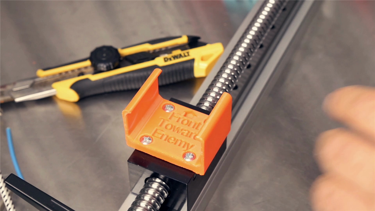
Designing Custom Mechanical Parts and Accuracy Testing
Although the evaluation kit provides its own magnetic assemblies, incorporating them into a practical mechanism required additional hardware.
OpenSCAD was used to design a shaft adapter that couples the supplied magnetic assembly to the ballscrew. A separate support bracket was designed in FreeCAD to hold the evaluation board, maintain sensor spacing and provide attachment points for the magnetic shielding ring.
The finished components are available as downloadable 3D models and make it considerably easier to integrate the evaluation hardware into experimental setups.To validate the system, measured travel was compared against readings from a laser distance meter.
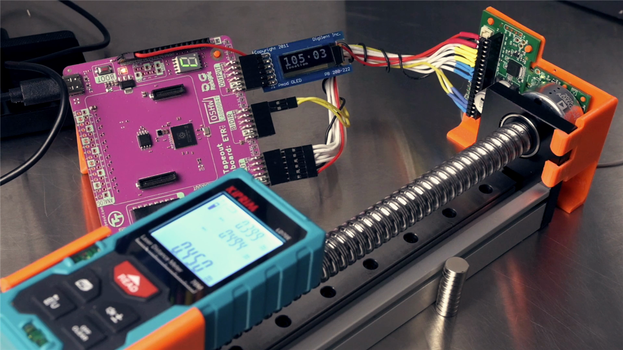
With a 5 mm pitch ballscrew, ten complete turns should produce exactly 50 mm of travel.
The measured displacement matched expectations, demonstrating that the sensor correctly tracked angular position across multiple revolutions while translating it into useful linear movement.
The ADMT4000 ultimately offered substantially finer resolution than the laser distance reference being used for verification.
Magnetic Shielding and Environmental Effects and Resetting the Turn Counter
Testing also highlighted the benefits of the supplied magnetic shield ring.
When installed, nearby external magnets produced minimal disturbance because magnetic flux naturally preferred travelling through the engineered magnetic circuit rather than through surrounding air.
Removing the shield made the system noticeably more susceptible to external magnetic influences.
"In production, especially in something industrial with lots of metal around, the ring is probably a good idea."
One unusual aspect of the ADMT4000 is that the turn count is not stored in volatile memory. It is represented by a physical magnetic state inside the device. Consequently, resetting the counter requires influencing those magnetic structures rather than simply writing a register.
Several methods were explored:
- A dedicated reset coil integrated into the evaluation board
- Applying a sufficiently strong external magnetic field
- Rotating beyond the maximum 46-turn range
The external magnetic field method proved particularly effective during experimentation and offered a useful way to visualise the sensor's underlying operating principles.
Final Thoughts
The ADMT4000 occupies a niche that few sensors can address. Its ability to preserve position information while completely unpowered eliminates the need for backup batteries, continual wake-ups, or homing procedures.
The project demonstrated not only how the device can be integrated into practical systems, but also revealed the remarkable material science that makes it work. Along the way it produced a complete MicroPython driver, OLED-based interface, custom mounting hardware and a collection of experiments exploring both AMR and GMR sensing principles.
For applications requiring immediate position awareness after power restoration, particularly where multiple revolutions must be tracked, the ADMT4000 offers capabilities that are difficult to achieve through conventional sensing approaches.
Additional project resources include the MicroPython driver implementation, the custom mounting bracket, and 3D-printable magnetic assembly adapters, making it much easier for others to explore this unusual sensor technology for themselves.
Supporting Links and Files
Products Used / Bill of Materials
| Product Name | Manufacturer | Quantity | Buy Kit |
|---|---|---|---|
| Multiturn Magnetic Sensor, 0.016T to 0.031T, 3V to 3.6V, -40°C to 125°C, TSSOP-24 | Analog Devices | 1 | Buy Now |
| Evaluation Kit, ADMT4000BRUZAB, Magnetic Turn Counter Sensor, Magnet Stimulus, Dipole Magnet | Analog Devices | 1 | Buy Now |
Additional Parts
| Product Name | Manufacturer | Quantity |
|---|---|---|
| magnet/shield nub for 3d printing | https://www.printables.com/model/1774156-admt4000-admagb3476-connector-for | 1 |
| bracket for mounting the eval board vertically | https://www.printables.com/model/1774230-bracket-for-admt4000-eval-board-eval-admt4000sd1z | 1 |


