
2.jpg.jpg-68x68x2.jpg?_=zqdYZYFj3EWNUExYxEhR6Q==)
Table of contents

Abstract
Hello makers and let's build something funny!
Project
Hello makers and let's build something funny!
I made a little project that's more funny than scary, "The third eye!" . Unfortunately, I can't say that it makes me wiser ( ) or that it helps me see better, but maybe it hypnotizes someone to give more candy (
 ).
).
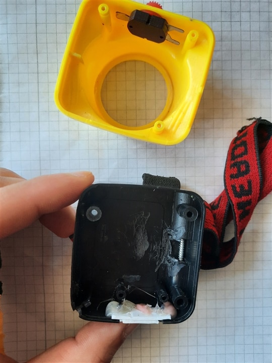
I started with a head lamp housing which, as you will see, I found another use for. I thought about incorporating an 8x8 LED matrix and illustrating some animations, that being said, an animated eye seems like a good and effective idea, given the available components. At the same time, I was put in a difficult position on the one hand by space, on the other hand I also made a small mistake, accidentally while working on this project I realized that I didn't make a very good purchase with a module (a previous purchase of mine, you'll see later), and this could affect the completion of the project.
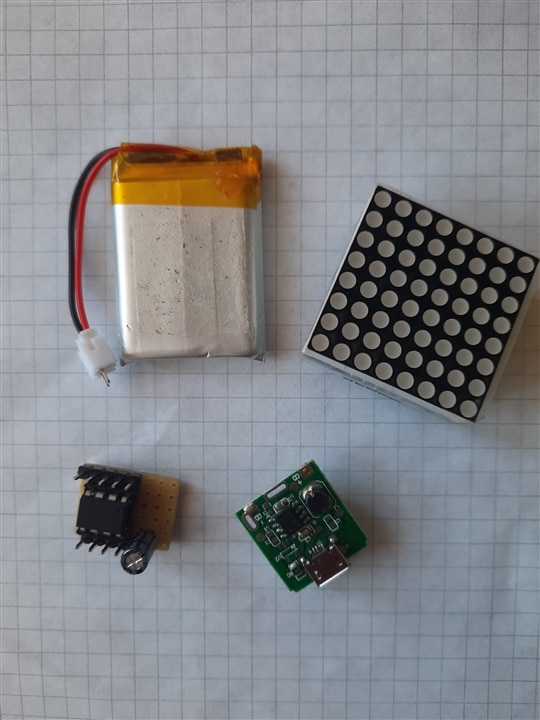
And now the list of components used:
• 1x head lamp housing;
• 1x 8x8 LED matrix;
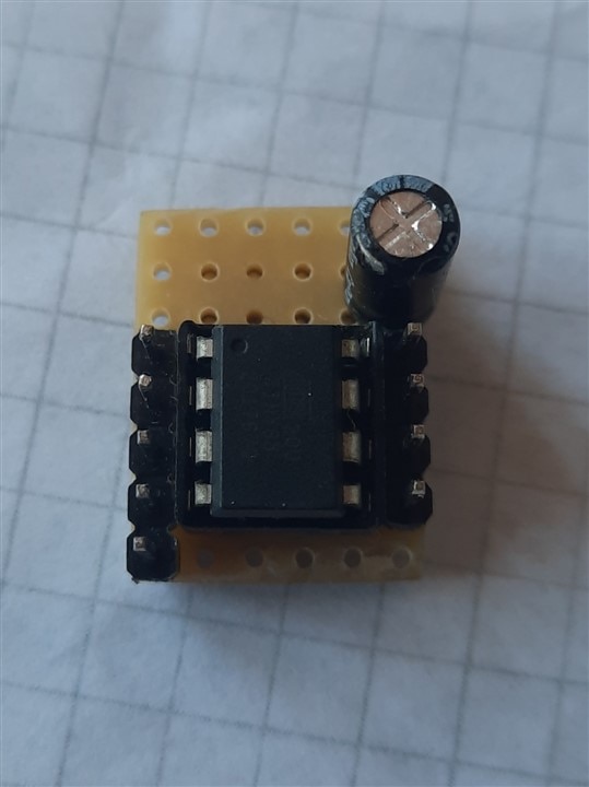
• 1x microcontroller (of course), Attiny85;
• 1x 3.7V battery;
• 1x charging board;
• 1x On/Off button.
I also consider the Arduino IDE for the software part. Not to mention the various tools used.
And a very concise diagram: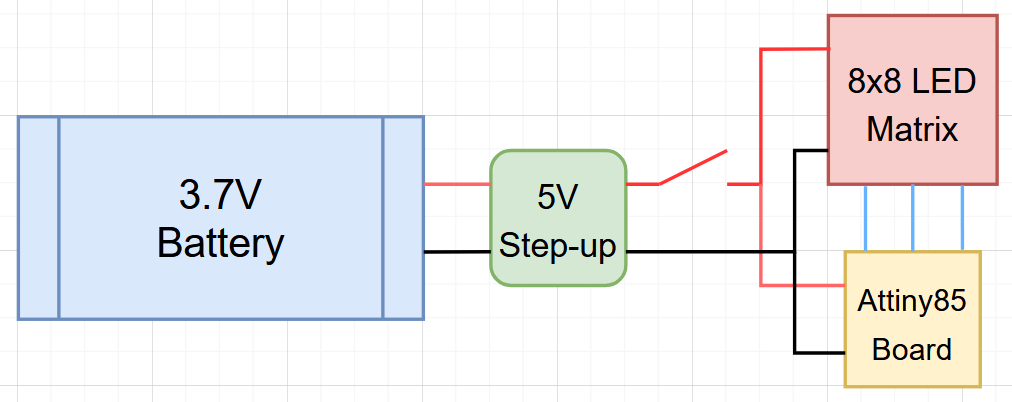
First, let me describe the microcontroller and programming part a little.
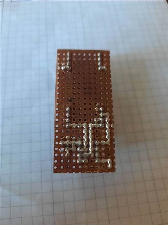
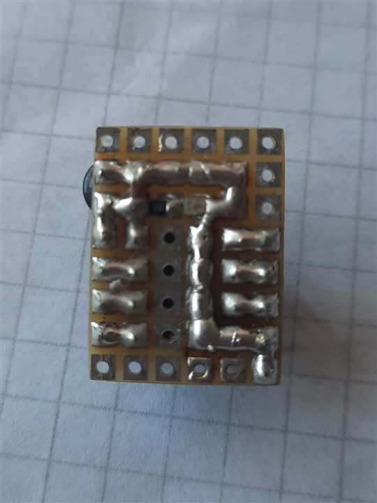
As I said above, I needed a microcontroller or a minimal board, so I chose Attiny85. I had built a small minimal board, with access to GPIOs and 2 capacitors on the power supply, and that's about it, which suited this project. For programming Attiny85 I used Arduino IDE, but since Attiny85 is not natively part of Arduino IDE, you need to follow a few steps.
Installing Attiny boards in Arduino IDE
http://drazzy.com/package_drazzy.com_index.json
The address above must be copied to Preferences in order to install the Attiny85 component in Arduino IDE (they must be separated by a comma "," from the others if there are any)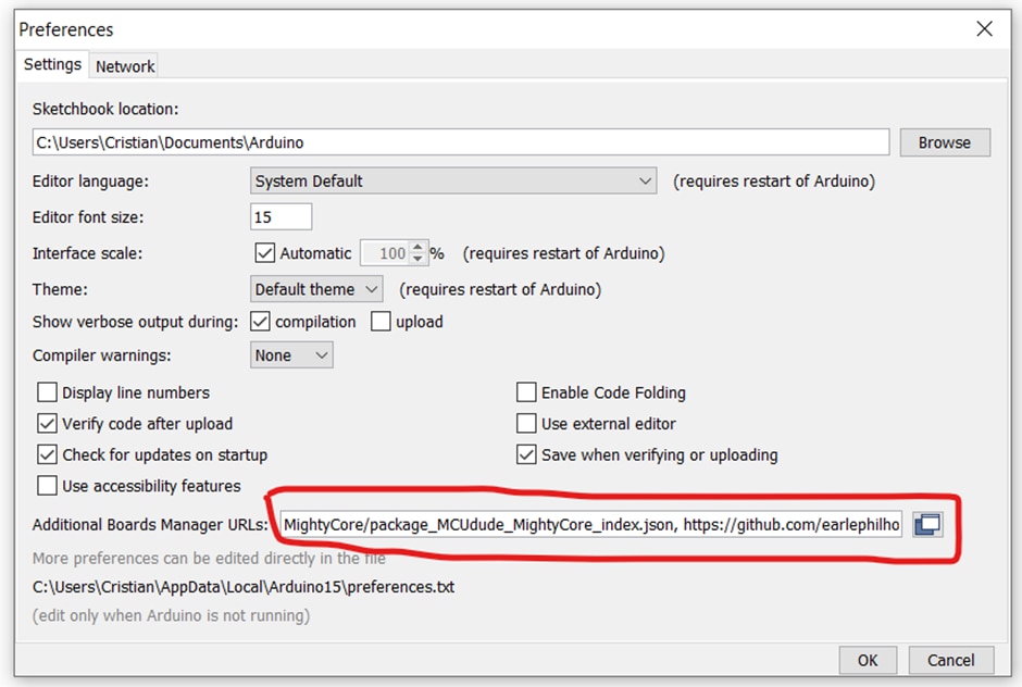
Then in Boards Manager I search for and install AttinyCore: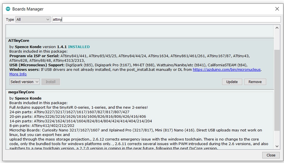
Or I manually download the archive from github: https://mcudude.github.io/MiniCore/package_MCUdude_MiniCore_index.json
Thanks to the author of this clip:https://www.youtube.com/watch?v=Z_MhVSlMZI8
Now we should be able to select Attiny85 as a board.
I used this method on Arduino IDE v1.8.19, I also tried on v2 but it didn't work, I don't know what the problem is.
Programming Attiny85 using Arduino IDE
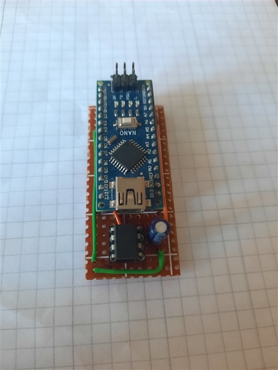
Furthermore I also used an Arduino Nano board on which I had already uploaded the "Arduino ISP" sketch. Connections between Attiny85 and Arduino Nano:
|
Arduino Nano Pins |
Attiny85 Pins |
|
5V |
Pin 8 → 5V |
|
GND |
Pin 4 → GND |
|
D10 → SS |
Pin 1 → Reset |
|
D11 → MOSI |
Pin 5 → MOSI |
|
D12 → MISO |
Pin 6 → MISO |
|
D13 → SCK |
Pin 7 → SCK |
Initially I tested it on a breadboard, then I soldered it on a test board to make it easier for me to use.
| {gallery}Test board |
|---|
|
Test board 1 |
|
Test board 2 |
Next, we open the program we want to load into the Attiny85:
• select board (Attiny82 no bootloader);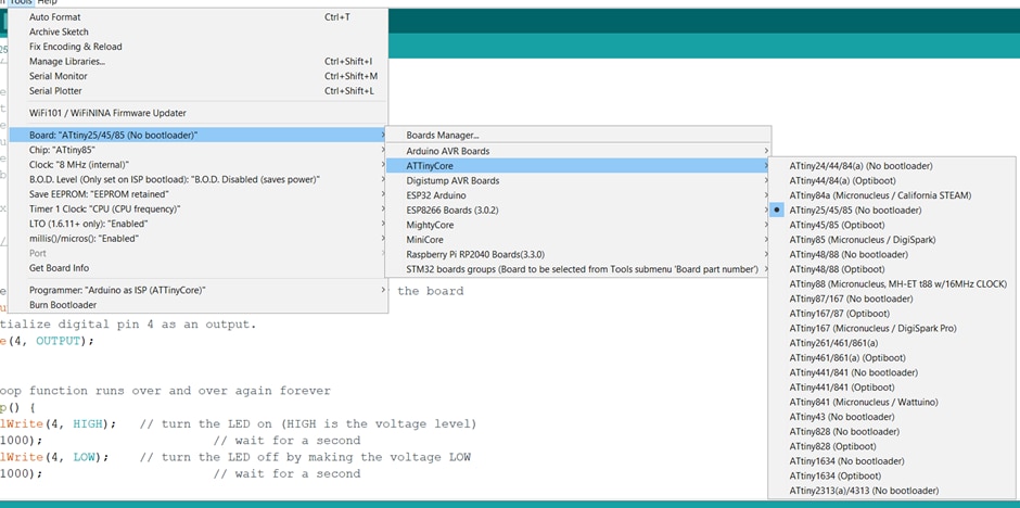
• then programmer (Arduino as ISP - AttinyCore);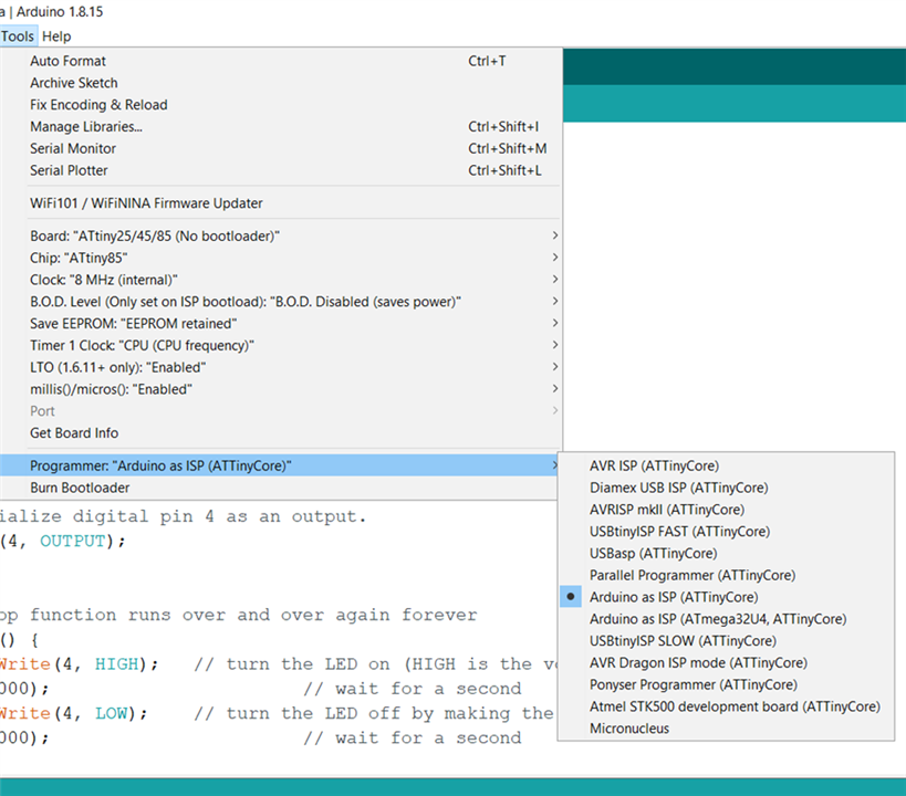
• click on Burn Bootloader (it should take about 2s, I noticed that I have to do this every time I want to upload a program);
• and finally click Upload Sketch, the "Blink" example worked perfectly.
Program used for this project:
/* Project: The third eye using ATTiny85 + 8x8 LED Matrix (MAX7219 driver)
   Participation in the "2025 Halloween Hackathon" - Element14 🙂
*/
#include <avr/io.h>
#include <avr/pgmspace.h>
#include <util/delay.h>

// Pin masks
#define DIN_PIN (1 << PB0)
#define CS_PIN (1 << PB1)
#define CLK_PIN (1 << PB2)

// Convenience macros
// Set the Data Input (DIN) pin high
#define DIN_HIGH() (P
// Set the Data Input (DIN) pin low
#define DIN_LOW() (PORTB &= ~DIN_PIN)
// Set the Clock (CLK) pin high
#define CLK_HIGH() (PORTB |= CLK_PIN)
// Set the Clock (CLK) pin low
#define CLK_LOW() (PORTB &= ~CLK_PIN)
// Set the Chip Select (CS) pin high (deselect device)
#define CS_HIGH() (PORTB |= CS_PIN)
// Set the Chip Select (CS) pin low (select device)
#define CS_LOW() (PORTB &= ~CS_PIN)

// MAX7219 registers
#define MAX_REG_NOOP 0x00
#define MAX_REG_DIGIT0 0x01
#define MAX_REG_DECODE_MODE 0x09
#define MAX_REG_INTENSITY 0x0A
#define MAX_REG_SCAN_LIMIT 0x0B
#define MAX_REG_SHUTDOWN 0x0C
#define MAX_REG_DISPLAY_TEST 0x0F

// Single matrix only
void maxSendByte(uint8_t data) {
  // MSB first
  for (uint8_t i = 0; i < 8; ++i) {
    if (data & 0x80) DIN_HIGH();
    else DIN_LOW();
    CLK_HIGH();
    // small delay to meet timing
    asm volatile("nop");
    CLK_LOW();
    data <<= 1;
  }
}

void maxWriteRegister(uint8_t reg, uint8_t value) {
  CS_LOW();
  maxSendByte(reg);
  maxSendByte(value);
  CS_HIGH();
  // tcs (chip select spacing)
  _delay_us(1);
}

void maxInit() {
  // ensure pins are outputs
  DDRB |= (DIN_PIN | CS_PIN | CLK_PIN);
  // default idle states
  CLK_LOW();
  DIN_LOW();
  CS_HIGH();

  maxWriteRegister(MAX_REG_SHUTDOWN, 0x01);      // Normal operation
  maxWriteRegister(MAX_REG_DISPLAY_TEST, 0x00);  // Disable test
  maxWriteRegister(MAX_REG_SCAN_LIMIT, 0x07);    // Display all 8 digits
  maxWriteRegister(MAX_REG_DECODE_MODE, 0x00);   // No decode, we send raw columns
  maxWriteRegister(MAX_REG_INTENSITY, 0x01);     // Low intensity
  // Clear display
  for (uint8_t i = 0; i < 8; ++i) maxWriteRegister(MAX_REG_DIGIT0 + i, 0x00);
}

void maxSetIntensity(uint8_t i) {
  if (i > 15) i = 15;
  maxWriteRegister(MAX_REG_INTENSITY, i);
}

// Sprites in PROGMEM
const uint8_t straight_eye[] PROGMEM = {
  8, 8,
  0b00000000,
  0b00111100,
  0b01111110,
  0b01100110,
  0b01100110,
  0b01111110,
  0b00111100,
  0b00000000
};

const uint8_t up_eye[] PROGMEM = {
  8, 8,
  0b00000000,
  0b00111100,
  0b01111110,
  0b01001110,
  0b01001110,
  0b01111110,
  0b00111100,
  0b00000000
};

const uint8_t down_eye[] PROGMEM = {
  8, 8,
  0b00000000,
  0b00111100,
  0b01111110,
  0b01110010,
  0b01110010,
  0b01111110,
  0b00111100,
  0b00000000
};

const uint8_t left_eye[] PROGMEM = {
  8, 8,
  0b00000000,
  0b00111100,
  0b01111110,
  0b01111110,
  0b01100110,
  0b01100110,
  0b00111100,
  0b00000000
};

const uint8_t right_eye[] PROGMEM = {
  8, 8,
  0b00000000,
  0b00111100,
  0b01100110,
  0b01100110,
  0b01111110,
  0b01111110,
  0b00111100,
  0b00000000
};

const uint8_t top_left_eye[] PROGMEM = {
  8, 8,
  0b00000000,
  0b00111100,
  0b01111110,
  0b01111110,
  0b01001110,
  0b01001110,
  0b00111100,
  0b00000000
};

const uint8_t bot_left_eye[] PROGMEM = {
  8, 8,
  0b00000000,
  0b00111100,
  0b01111110,
  0b01111110,
  0b01110010,
  0b01110010,
  0b00111100,
  0b00000000
};

const uint8_t top_right_eye[] PROGMEM = {
  8, 8,
  0b00000000,
  0b00111100,
  0b01001110,
  0b01001110,
  0b01111110,
  0b01111110,
  0b00111100,
  0b00000000
};

const uint8_t bot_right_eye[] PROGMEM = {
  8, 8,
  0b00000000,
  0b00111100,
  0b01110010,
  0b01110010,
  0b01111110,
  0b01111110,
  0b00111100,
  0b00000000
};

const uint8_t blink_eye[] PROGMEM = {
  8, 8,
  0b00000000,
  0b00000000,
  0b00000010,
  0b00000010,
  0b00000010,
  0b00000010,
  0b00000000,
  0b00000000
};

// Helper to write an 8x8 sprite stored in PROGMEM
void maxWriteSprite8x8(const uint8_t *spriteProgmem) {
  // First two bytes are width,height in original; skip them
  // sprite data columns/rows are stored row-wise as provided (8 rows).
  // MAX7219 digit registers map 1..8 to columns (or rows depending on wiring). Here we
  // write row bytes to DIGIT0..DIGIT7.
  uint8_t w = pgm_read_byte(spriteProgmem);      // width (unused)
  uint8_t h = pgm_read_byte(spriteProgmem + 1);  // height (unused)
  (void)w;
  (void)h;
  for (uint8_t row = 0; row < 8; ++row) {
    uint8_t b = pgm_read_byte(spriteProgmem + 2 + row);
    // MAX7219 digits are 1..8
    maxWriteRegister(MAX_REG_DIGIT0 + row, b);
  }
}

int main(void) {
  maxInit();
  maxSetIntensity(1);

  const uint8_t *sequence[] = {
    straight_eye,
    up_eye,
    top_left_eye,
    straight_eye,
    blink_eye,
    straight_eye,
    blink_eye,
    straight_eye,
    down_eye,
    bot_right_eye,
    straight_eye,
    blink_eye,
    straight_eye,
    blink_eye,
    straight_eye,
    left_eye,
    bot_left_eye,
    straight_eye,
    blink_eye,
    straight_eye,
    blink_eye,
    straight_eye,
    right_eye,
    top_right_eye,
    straight_eye,
    blink_eye,
    straight_eye,
    blink_eye
  };

  // timings in milliseconds corresponding to the original sequence
  const uint16_t times[] = {
    2000, 2000, 2000, 700, 700, 700, 1000,
    2000, 2000, 2000, 700, 700, 700, 1000,
    2000, 2000, 2000, 700, 700, 700, 1000,
    2000, 2000, 2000, 700, 700, 700, 1000
  };

  // Simple main loop
  while (1) {
    for (uint8_t i = 0; i < (sizeof(sequence) / sizeof(sequence[0])); ++i) {
      maxWriteSprite8x8(sequence[i]);
      // delay in ms using _delay_ms (max param compile-time constant in util/delay)
      // Use simple loop for variable delay
      uint16_t ms = times[i % (sizeof(times) / sizeof(times[0]))];
      while (ms--) _delay_ms(1);
    }
  }

  return 0;
}
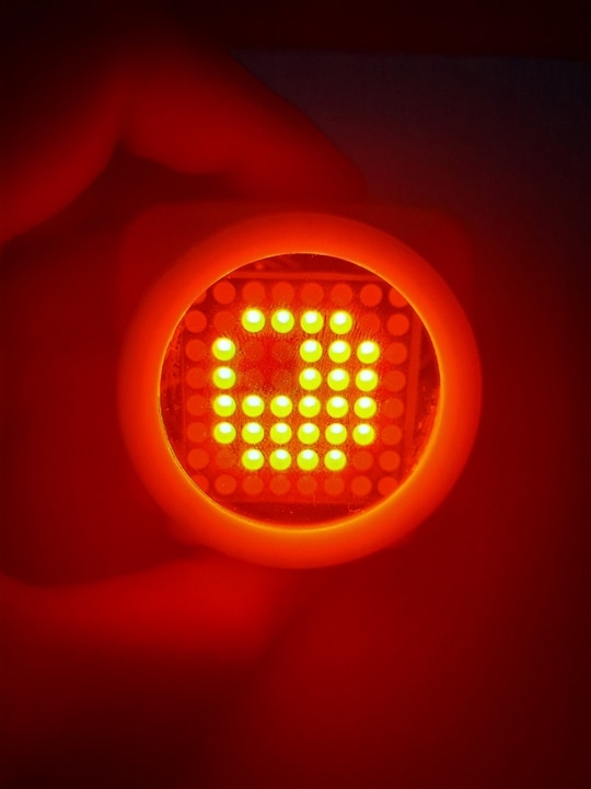
I created some animations (frames) on the "eye" model that fit on the 8x8 matrix and the program actually cycles through these animations: straight; up-down-left-right; top left-down left; top right-down right; and blinking effect. Link to generator: https://xantorohara.github.io/led-matrix-editor/
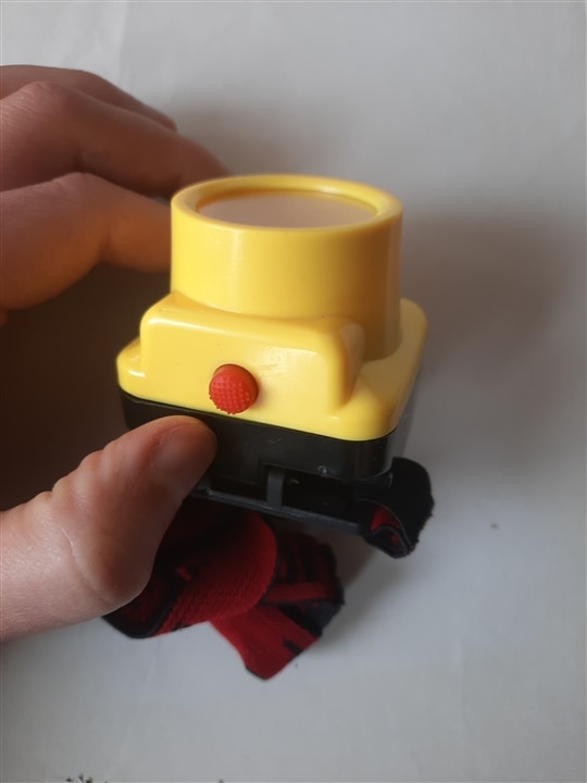
Initially I tested on an Arduino Nano board and then I thought about Attiny85. I should mention that I also used an AI to make the transition from Arduino Nano to Attiny85 and to save time.
Let's talk a little about the manual work.
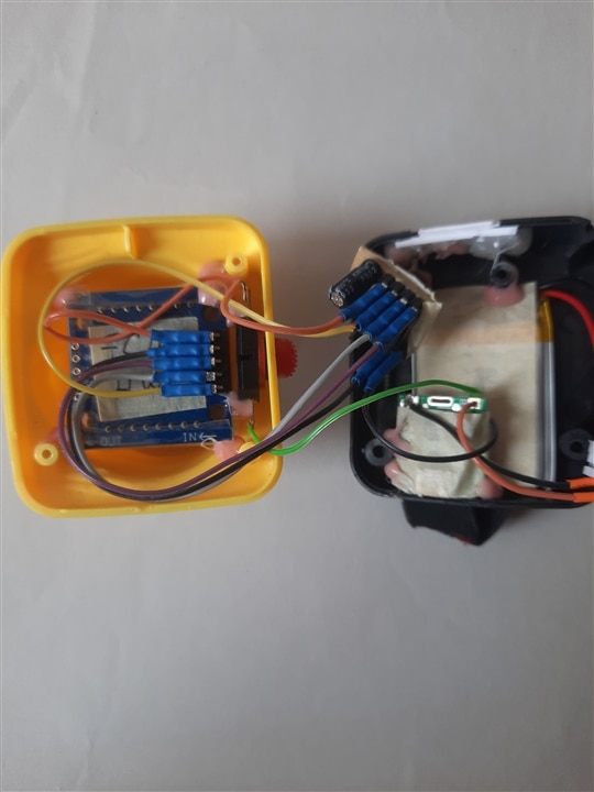
The head lamp housing fit almost perfectly, being square like the LED matrix, but it still had to be modified a little on the inside (cutting a few elements) to make more space for the components, which are already cramped, but I used thin and flexible wires and that helped me.
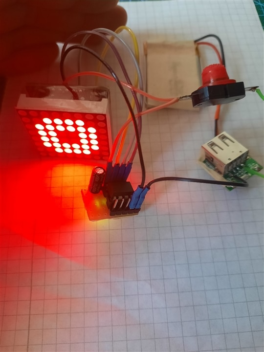
Since the LED matrix and Attiny85 work optimally at 5V, and the battery is 3.7V, I introduced a module that also contains a step-up converter into the circuit. So I connected the battery to the step-up module to obtain 5V with which I power the circuit. I also mention the use of an On/Off button mounted between the output of the step-up and the matrix+Attiny. Sometimes the step-up module does not work very well, that is, it stops. Unfortunately, I don't have another small step-up converter at the moment (but I will add it to the shopping list), so the current one remains in use, but in the future I will have to find a better one.
Another small modification, I unsoldered the header pins on the matrix and put others on the back, right angle type. Other notes, well, soldering short wires hurts. 
As you will see in the pictures, I also used the indispensable hot glue to fix the components more conveniently. Again, a little poorly assembled, but I think it will hold up.. 
| {gallery}Project pictures |
|---|
|
Attiny85 minimal board 1 |
|
Attiny85 minimal board 2 |
|
Components |
|
Preliminary test |
|
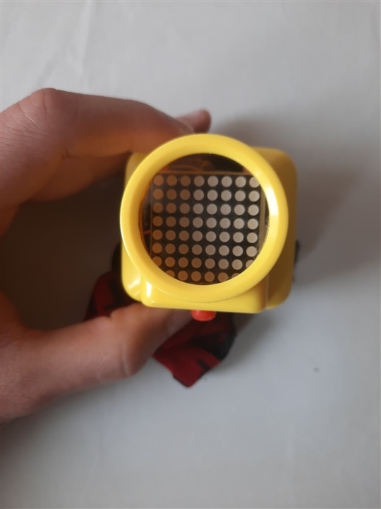
Head lamp enclosure |
|
Assembly 1 |
|
Assembly 2 |
|
Assembly 3 |
|
Assembly 4 |
And a short video:
What do you think, did this project hypnotize you in any way?


Good luck collecting treats!