

Table of contents

Abstract
A speaker disguised as a rock plays scary sounds, triggered by a motion sensor when those pesky little Trick-Or-Treaters approach.
Project
History
A long time ago in a lab far, far away a Halloween prop was built with the name Scare-O-Matic and scared young and older trick-or-treaters. It was a small box with a motion sensor and a tiny 1 watt amplifier and speaker. But as time went on, it went up in smoke and was no more. Shortly after a much larger speaker arrived by mail and was waiting for a project. The time is now. Those are the voyages which lead to Scare-O-Matic 2026 Edition.
I already had the following parts:
Speaker: Stellar Labs 50-14910
MP3 player: DFPlayer Mini
Motion Sensor: Panasonic EKMC7604111K
Analog shenanigans
Initially my plan was to build a simple analog circuit with the components at hand. I needed a pulse generator, as the MP3 player only allowed a certain short length of pulse to trigger playing the next tune. A long pulse on the same input generated a volume up signal. Nice usability but not helpful for me. The idea to gate the motion signal only with the idle signal was not usable. The pulse generator worked OK in simulation, but I could not make the real circuit work. Mostly because of lack of test equipment, I am still missing an oscilloscope to measure all the signals. (Road-test crew, when will Siglent or Tektronix sponser the next roadtest?). Here is the LTSpice model for your viewing pleasure. 

I already hear the voices in my head: "Could have used a 555!!" Yes, but I did not have one. Just a sad picture of the leftover analog circuit, a colourful mix of through hole and SMT parts.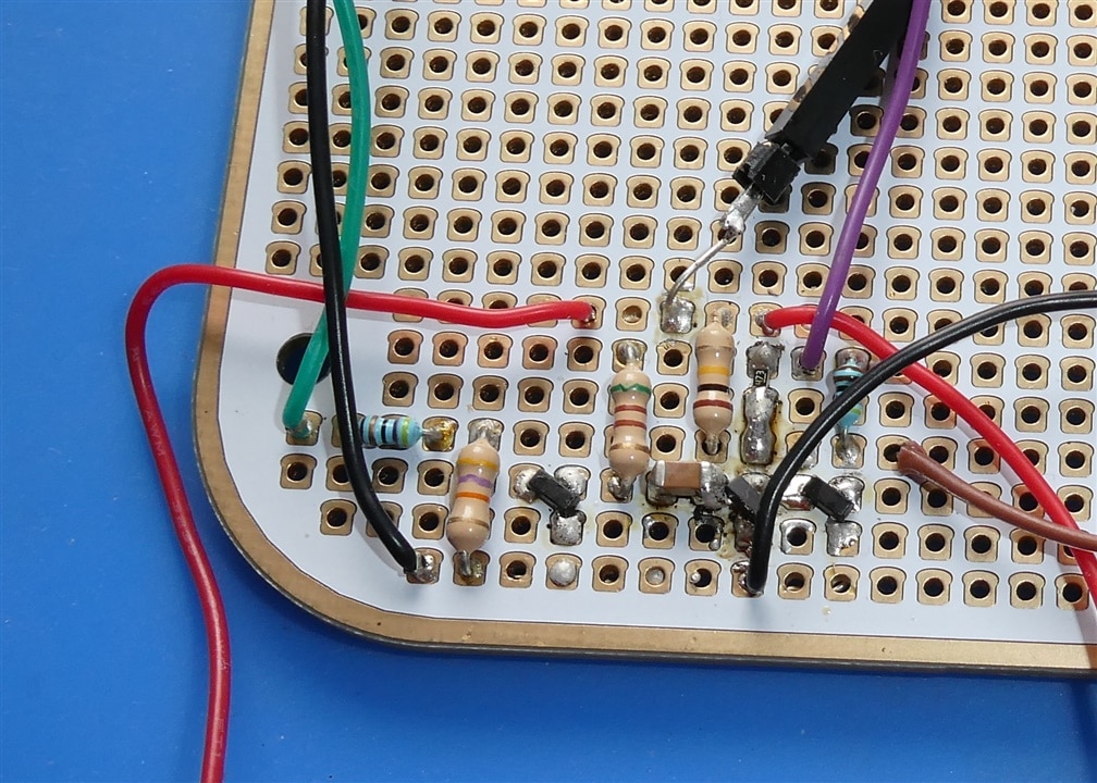
The good parts, the bad firmware and the ugly build
In the end I went back into the digital galaxy and used a trusted Arduino Uno R4 and built a shield with inputs from the motion sensor and the IDLE signal from the MP3 player and outputs to the player to control the playing of the samples and the volume. Some might notice the funny shape of the 'breadboard'. Kudos to the folks over at Breadstick Innovation, who send you a prototoast with every order, which does not only have the shape of a slice of bread. The through hole pads are also this shape. Brilliant marketing.

Here is the code:
// SCARE-O-MATIC Edition Halloween 2026
// by Wolfgang Friedrich
//    30. Oct 2026
// Target: Arduino Uno R4


//#include <Arduino.h>

#define N_PREV_VOLDOWN 5
#define N_NEXT_VOLUP   6
#define IDLE           7
#define TRIGGER        3
#define LED           13
#define BUTTON0        0
#define BUTTON1        1


void setup() {
uint8_t seconds;


	Serial.begin(115200);
  // while(!Serial){};

  // put your setup code here, to run once:
  pinMode(N_PREV_VOLDOWN, OUTPUT);
	digitalWrite(N_PREV_VOLDOWN, LOW);
  pinMode(N_NEXT_VOLUP, OUTPUT);
	digitalWrite(N_NEXT_VOLUP, LOW);
  pinMode(LED, OUTPUT);
	digitalWrite(LED, LOW);

  pinMode(IDLE, INPUT);
  pinMode(TRIGGER, INPUT);
  pinMode(BUTTON0, INPUT);
  pinMode(BUTTON1, INPUT);

 	Serial.println("Halloween 2026 is ready!");


//*    Disable volume set when 1st '/' is removed; 2 '/' enable code
// set volume; very long pulse to turn off first, then pulse to set correctly.
// down 5 counts up 10 counts is nice low volume for development and not to scare the cats/neighbors!!
  digitalWrite(N_PREV_VOLDOWN, HIGH);
  for (seconds=0; seconds<3; seconds++) {       // 3 seconds makes a very low default volume
    delay(500);
    digitalWrite(LED, not digitalRead(LED));
    delay(500);
    digitalWrite(LED, not digitalRead(LED));
   	Serial.print("VOL down : ");
  	Serial.println(digitalRead(N_PREV_VOLDOWN));
  }
  digitalWrite(N_PREV_VOLDOWN, LOW);
/*
// 600 msec; every loop is 200 msec
  digitalWrite(N_NEXT_VOLUP, HIGH);
  for (seconds=0; seconds<4; seconds++) {
    delay(100);
    digitalWrite(LED, not digitalRead(LED));
    delay(100);
    digitalWrite(LED, not digitalRead(LED));
   	Serial.print("VOL up : ");
  	Serial.println(digitalRead(N_NEXT_VOLUP));
  }
  digitalWrite(N_NEXT_VOLUP, LOW);
// */

}

void f_ReadPins(void) {

	Serial.print("IDLE: ");
	Serial.print(digitalRead(IDLE));
	Serial.print(" - Trigger: ");
	Serial.print(digitalRead(TRIGGER));
	Serial.print(" - Next: ");
	Serial.print(digitalRead(N_NEXT_VOLUP));
	Serial.print(" - Prev: ");
	Serial.print(digitalRead(N_PREV_VOLDOWN));
	Serial.print(" - Button0: ");
	Serial.print(digitalRead(BUTTON0));
	Serial.print(" - Button1: ");
	Serial.print(digitalRead(BUTTON1));
  Serial.print("\r\n");

}


void loop() {

uint8_t counts;


  // detect trigger active and pulse next signal to play next track
  if ( digitalRead(IDLE)  && digitalRead(TRIGGER)) {
    digitalWrite(N_NEXT_VOLUP, HIGH);
    digitalWrite(LED, not digitalRead(LED));
	Serial.print("\r\n - Next: ");
	Serial.print(digitalRead(N_NEXT_VOLUP));
 	Serial.println(F(" - Next triggered!"));
    delay(200);
    digitalWrite(LED, not digitalRead(LED));
    digitalWrite(N_NEXT_VOLUP, LOW);
    delay(100);
  }


  // detect button on input 0 for manual volume up
  if ( digitalRead(IDLE)  && (!digitalRead(BUTTON0))) {
    digitalWrite(N_NEXT_VOLUP, HIGH);
    f_ReadPins();
      Serial.print("Next/VOL up : ");
      Serial.println(digitalRead(N_NEXT_VOLUP));
    digitalWrite(LED, not digitalRead(LED));
    while (!digitalRead(BUTTON0)) {};
    digitalWrite(LED, not digitalRead(LED));
    digitalWrite(N_NEXT_VOLUP, LOW);
  }

  // detect button on input 1 for manual volume down
  if ( digitalRead(IDLE)  && (!digitalRead(BUTTON1))) {
    digitalWrite(N_PREV_VOLDOWN, HIGH);
    f_ReadPins();
      Serial.print("Prev/VOL down : ");
      Serial.println(digitalRead(N_NEXT_VOLUP));
    digitalWrite(LED, not digitalRead(LED));
    while (!digitalRead(BUTTON1)) {};
    digitalWrite(LED, not digitalRead(LED));
    digitalWrite(N_PREV_VOLDOWN, LOW);
  }

  f_ReadPins();

  delay(100);

}
Testing and improvements
Testing showed good results, that I declared this my final solution. Until it got really annoying to set the volume by changing the code and reprogramming the R4. So I added 2 buttons and some more code, which proved to be very useful immediately. It was even buttons with benefits as I could not only increase and decrease the volume, but I could also test the sounds by pressing the buttons only for a short time to trigger a next track pulse instead of a volume up pulse duration. Double win.
The absolute max volume from the 3 W amplifier was not very loud and scary. I thought about adding a bigger amp, but then the flash of inspiration hit and I had a closer look at the sound samples. Most of them had a max signal amplitude of about 0.2 full scale. It was an easy fix to scale the wave-forms to full scale and get much more umpf out of the speaker. Sufficient to blast sweet demanding visitors. And I still have the option to crank it up to 11 by adding a bigger amplifier.
Test setup on the bench and quality check by the descendant of the Cat-Sith. This witchcraft device was approved by the feline supervisor.
.


Installation
Biggest question is, where to point the motion sensor? If I point it to the street, it will go off with every car or dog walker. Which would be fun for me but not so much for the dogs. Or I point it to the entrance from above to scare the little humans when they are trapped between the hope for candy and the Scare-O-matic. I think the 2nd one is the way to go. We'll see tomorrow.
And here is an audio clip of all sounds played back-to-back.
.
References
Scare-O-Matic 1st Edition:
https://hackaday.io/project/3238-scare-o-matic
Datasheets:
Motion sensor
MP3 player
Speaker

