

Table of contents

Abstract
Seven spooky games. One handmade console. Dead Channel combines Raspberry Pi 5, ESP32, Arduino Uno and Nano with a joystick, tuning knob, keypad, lights, buzzer and physical displays to bring a browser-based Halloween arcade into the real world.
Project
I built a little Halloween arcade, and it ended up taking over my desk.
It’s called Dead Channel. There are seven games, an iPad for the screen, and a breadboard console with a joystick, tuning knob, keypad, buttons, lights, a buzzer, an LCD and a seven-segment display. A Raspberry Pi 5 hosts it, with an ESP32, Arduino Uno and Arduino Nano handling the things on the desk.
The games range from keeping a ghost in the air to trying to answer calls from people who probably shouldn’t still have a telephone connection. I wanted something people could sit down and play for Halloween, and something that gave the electronics a job beyond just looking spooky.
Here it is in action: Watch the project video
You can also play it in your browser or look through the code and build files on GitHub.
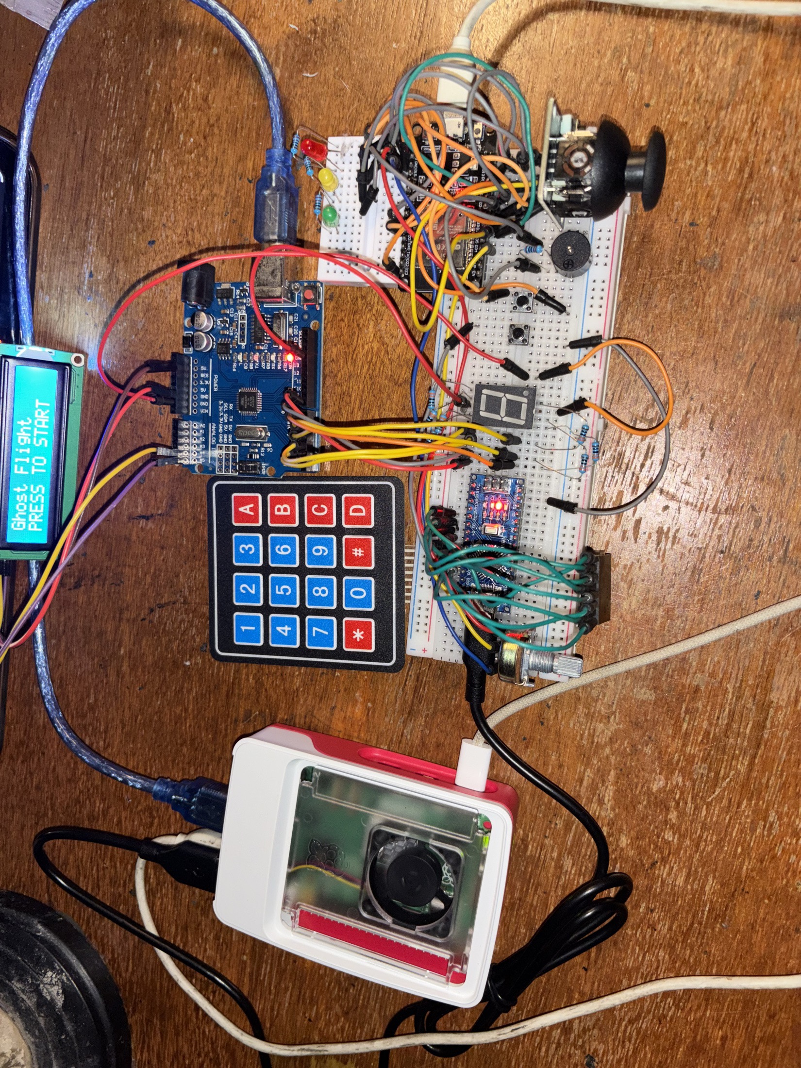
The actual setup. The LCD is on the Ghost Flight start screen here. All seven games share this console.
What can you play?
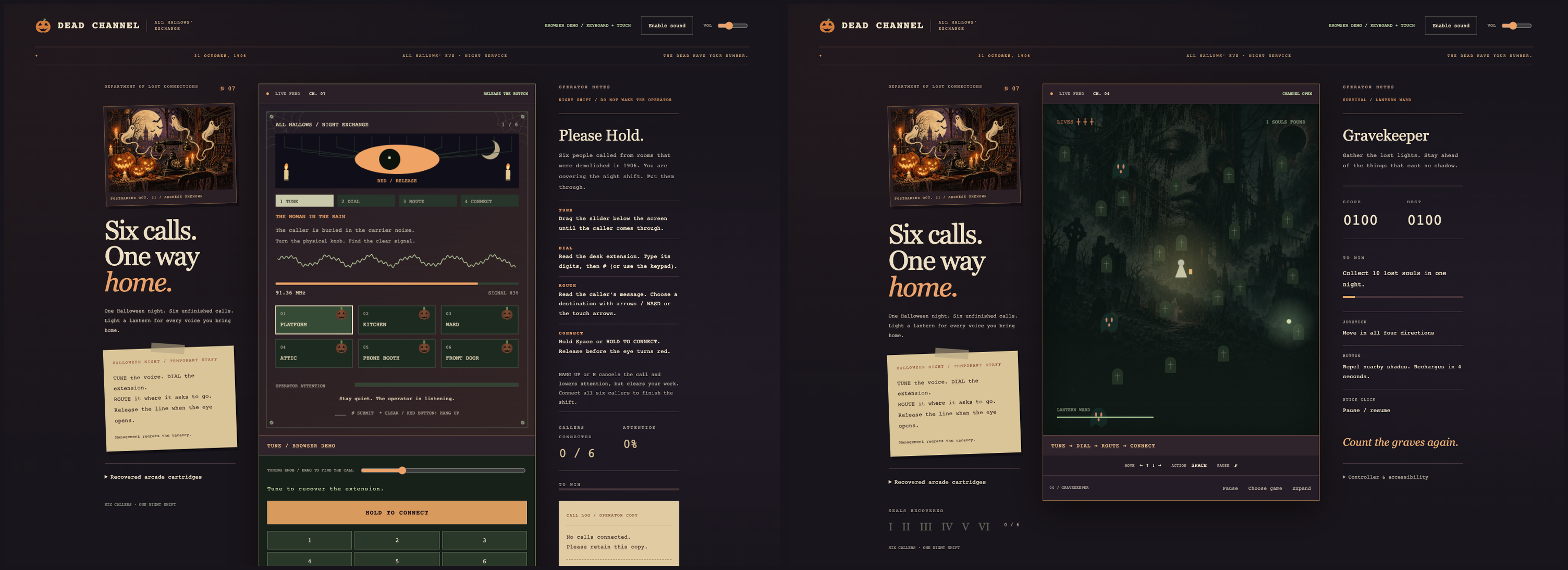
Two games from the deployed browser version: Please Hold on the left, Gravekeeper on the right.
Ghost Flight is the one where you tap the button to keep a ghost airborne and squeeze between cursed towers. Getting through eight towers clears it. It’s a simple control, but there’s plenty of room to mistime a flap.
Boot Breaker gives you a paddle and a bouncing boot. You move with the joystick, launch with the button, and try to knock out all 30 headstones in the first crypt.
Blimp Jump is a climbing game. You steer between platforms and work your way up to 1,000 metres. The button gives you an emergency lift, but it takes four seconds to recharge, so it can’t rescue every bad landing.
Gravekeeper puts you in a cemetery with a lantern and ghosts coming after you. You need to collect ten lost souls while keeping away from them. The button repels nearby ghosts when the ward is ready.
The Last Signal is a shooter. Move the transmitter, hold the button to fire, and stop the incoming contacts from reaching the line. Clearing 20 contacts wins the round.
Dead Frequency uses the tuning knob. Six voices are trapped between stations, and you have to find a clean signal and lock onto each one before you lose all three fuses. This was a nice reason to give the console an actual dial instead of making everything another joystick action.
Then there’s Please Hold, which uses the whole console as a haunted telephone exchange. You’re covering a Halloween night shift, trying to get six callers home while something on the other end keeps opening its eye.
You turn the knob until a call comes through, read the extension on the LCD, type it on the keypad and press #. After that, you have to read the caller’s message and work out where they want to go. The right extension only gets you access to the call; it doesn’t choose the destination for you.
Once you’ve picked a destination with the joystick, hold the main button to connect. Green is safe. Yellow is your warning. When the eye opens and the red LED comes on, let go. You can finish the connection in pieces, so releasing at the right time is part of playing.
The separate hang-up button gets you out of trouble, but it also throws away that call’s authorization and connection progress and gives you a different extension. As you get callers home, the digit on the desk counts down from six to zero.
The radio frequencies are part of the game, by the way. The knob is a potentiometer read by the ESP32, not an actual radio receiver.
Under all those wires
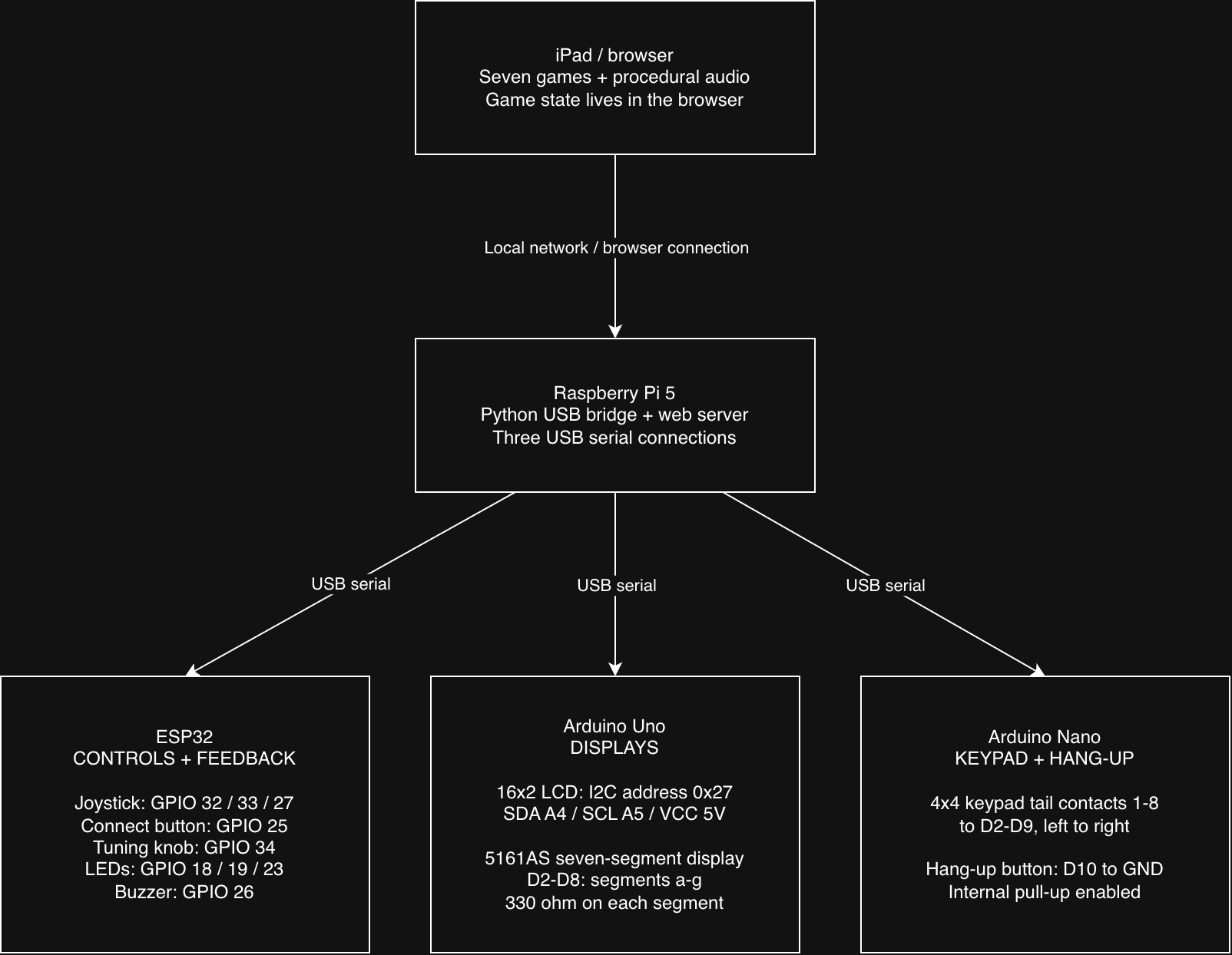
The console at a glance. Connection map made in diagrams.net; the pin-by-pin wiring is below. The arrows show connections, and data travels both ways.
The browser runs the games. The Pi serves the files and runs a small Python bridge that talks to the three boards over USB. The iPad connects to the Pi over the local network. Once the Pi is set up, the Mac I used for development doesn’t have to stay connected.
The ESP32 reads the joystick, its push switch, the tuning knob and the main action button. It also handles the three LEDs and buzzer. The Uno drives the 16×2 LCD and the 5161AS seven-segment display. The Nano scans the 4×4 keypad and the separate hang-up button.
Could I have used fewer boards? Yes. This is a modular breadboard prototype. Keeping the stations separate let me work on the keypad or display without rebuilding the rest of the controls. The trade-off is right there in the photos: more USB cables, more wiring, and more things to identify when a device reconnects.
The LCD and LEDs also do different jobs. In Please Hold, the LCD keeps the call information visible while the LEDs show whether it’s safe to connect. I wanted the player to look between the screen and the equipment, rather than have every display repeat the same warning.
Besides the four boards and iPad, the build uses an analog joystick, a potentiometer, a membrane keypad, two external push buttons, three LEDs, a two-pin buzzer, the LCD, the single-digit display, breadboards, jumpers and three USB data cables. There are ten nominal 330-ohm resistors: one for each LED and one for each of the seven display segments. The prototype buzzer branch has a 1-kilohm series resistor.
The Pi has its own USB-C supply, and its USB ports supply the microcontroller boards. The joystick and potentiometer run from the ESP32’s 3.3 V rail. The LCD is on the Uno’s 5 V side. There isn’t a direct 5 V signal connection from an Arduino into the ESP32, and the final setup doesn’t use a 9 V battery.
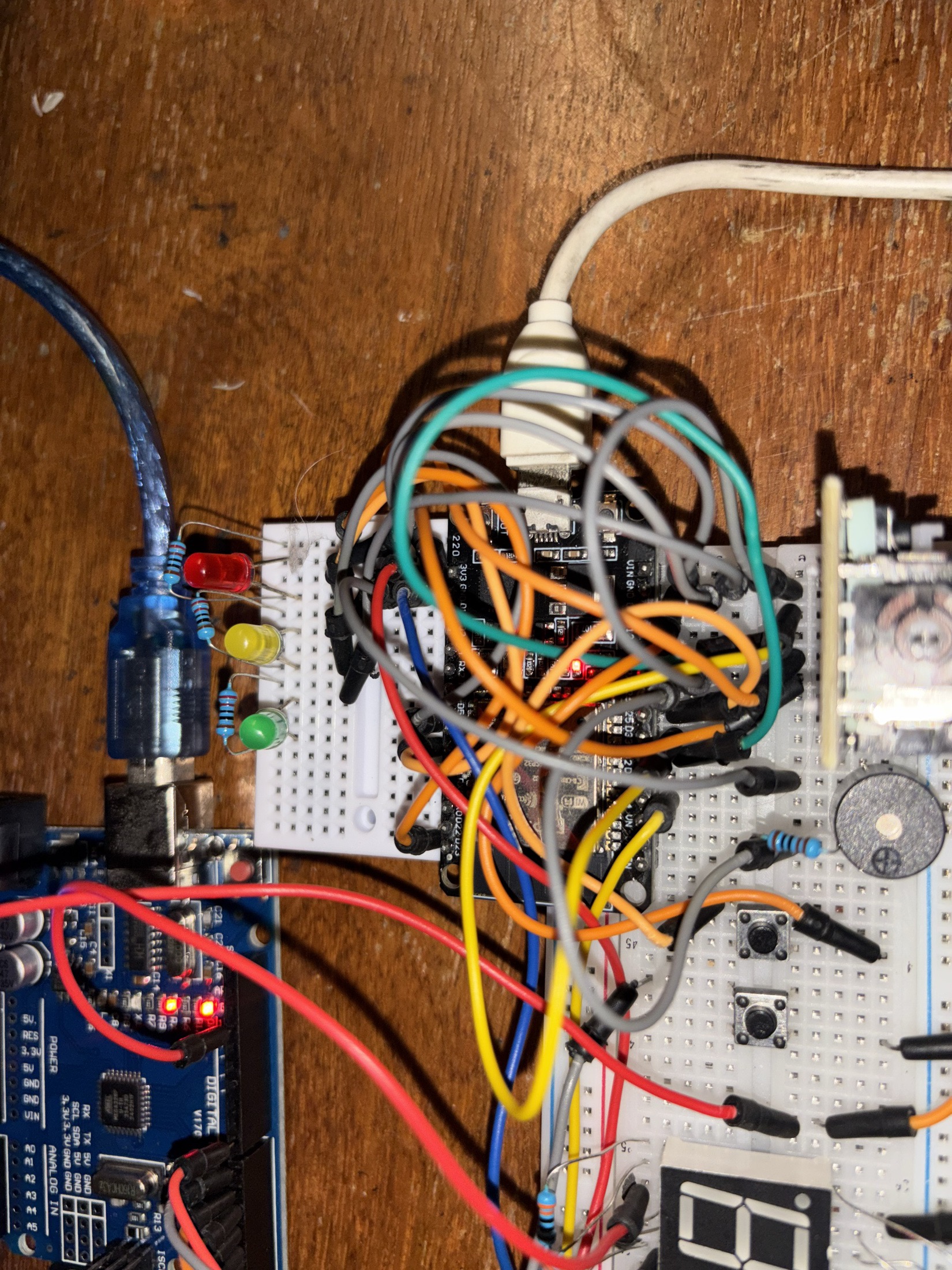
The control side of the prototype. The pin notes below are more useful for rebuilding it than trying to follow every overlapping wire in this photo.
If you want to build one
The build guide and wiring netlist are in the repository. Here are the connections in plain text too. Disconnect power before moving wires, and check the actual pin labels on your board.
On the ESP32, joystick VRx goes to GPIO32, VRy to GPIO33 and the joystick switch to GPIO27. The main button goes between GPIO25 and ground. Both switches use internal pull-ups. The potentiometer’s outer terminals go to 3V3 and ground, with the wiper on GPIO34. The firmware averages and smooths the knob reading.
The green, yellow and red LEDs go to GPIO18, GPIO19 and GPIO23 respectively, each through its own 330-ohm resistor, with the cathode to ground. The buzzer branch used here is GPIO26 → 1 kilohm → buzzer positive, with the other lead to ground. I haven’t identified the buzzer’s exact electrical type, so check the requirements of your own part and use a suitable driver if it needs one.
On the Uno, the LCD uses 5 V and ground, SDA on A4 and SCL on A5. This backpack is at address 0x27. I used Bill Perry’s hd44780 library, version 1.3.2.
The 5161AS is common cathode. Looking at its front with the decimal point at bottom right, common pins 3 and 8 go to ground. Uno D2 through D8 drive segments a through g through seven separate 330-ohm resistors. In that order, the display pins are 7, 6, 4, 2, 1, 9 and 10. Decimal-point pin 5 isn’t used.
For the Nano, hold the keypad facing you with the tail pointing down. Its eight contacts, left to right, connect to D2 through D9. My corrected firmware uses rows 9, 8, 7, 6 and columns 5, 4, 3, 2. That mapping is for this keypad; check every key on yours. The hang-up button goes between D10 and ground, with the internal pull-up enabled.
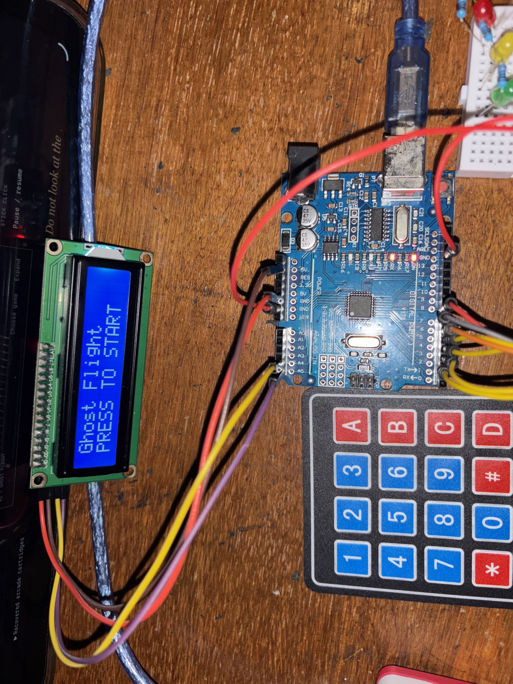
The Uno and LCD. The keypad next to them is connected to the separate Nano.
Flash the ESP32 with firmware/haunted_controller/haunted_controller.ino, the Uno with firmware/lcd_station/lcd_station.ino, and the Nano with firmware/keypad_station/keypad_station.ino. You’ll need the matching ESP32 and AVR board cores and the hd44780 library for the Uno.
Connect all three boards to the Pi with USB data cables and identify their serial ports. Persistent /dev/serial/by-id/ paths help avoid mixing the boards up after reconnecting them. The stations communicate at 115200 baud.
Run the bridge with your own device paths:
python3 server.py --serial /dev/serial/by-id/YOUR_ESP32 --lcd-serial /dev/serial/by-id/YOUR_UNO --keypad-serial /dev/serial/by-id/YOUR_NANO
Then open http://PI_LAN_ADDRESS:8765/ on the iPad or another device on the same local network. The server uses Python’s standard library. Node.js 22 or later is used for the software build and tests.
Before playing, check the joystick directions, knob travel, buttons, individual LEDs, readable LCD text, digits 0–9 and every keypad key. The game has controller settings and output tests to help with this. Run joystick direction learning on each browser you use, since the calibration is stored separately.
If you just want to try the games, the public browser version has keyboard and touch controls. It runs on your own device and doesn’t connect to my physical console.
The bits that fought back
The LCD was a good reminder that a backlight doesn’t mean the display is working. Loose connections could leave it lit or showing blocks. Later, its I2C address would respond while initialization still failed. The library’s automatic instance search was advancing across retries, so explicitly setting the known 0x27 address fixed that retry problem. Reporting the I2C status and initialization status separately made it much easier to tell what was happening.
The keypad was backwards in software at first. Pressing 1, 2, 3, 4 gave me D, C, B, #. Changing the row and column mapping fixed the decoding without having to reverse the assembled wiring again.
I also had the seven-segment wires on the wrong Arduino. It was sitting near the Nano, but the display code was running on the Uno. Moving the wires to the right board and completing the ground connection got the digit test working.
There was a Pi USB host-controller fault too: the ESP32 and Uno disappeared while the Nano stayed connected. A clean reboot brought all three back. The kernel reported the controller failure, but I haven’t established what caused it.
The software currently passes all 30 automated tests. Those cover the arcade rules, display behavior and the telephone game, including a simulated six-caller run. Browser checks also reached the ending and exercised pause, saving and small-screen layouts. I keep those separate from physical testing: a passing test doesn’t tell me whether a breadboard wire is loose.
There’s still stuff I’d improve. A labelled enclosure and better connectors would make this much easier to move around. I’d also identify the buzzer properly, measure current and response time, retain a complete all-key check, and put the console through longer physical sessions.
For now, I’m happy that the same collection of parts can be a flight game, a crypt-breaking game, a ghost chase, a radio and a haunted switchboard. It’s a slightly ridiculous amount of wiring for a Halloween arcade, but that’s also been a big part of the fun.
If you try it, I’d like to know which game you get stuck on first.
Project video · Play Dead Channel · Code and build files
Built by Adriel Magalona. Browser audio is procedural. Thanks to the Arduino and ESP32 toolchain authors and Bill Perry for the hd44780 library.
References
Project resources
- Dead Channel — project demonstration
- Playable browser edition
- Source code, firmware and build documentation
- Portable build guide
- Pin-level wiring netlist
- Validation record
Library acknowledgement
Bill Perry / duinoWitchery — hd44780 LCD library, version 1.3.2 used in this build.
Top Comments