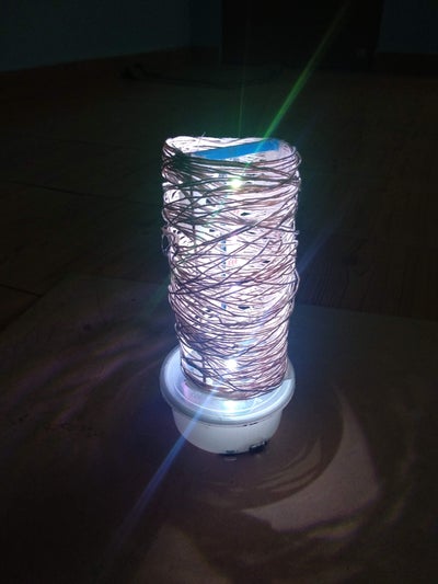
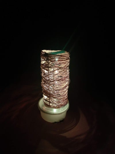
About 230 thousand years ago human being learnt to control the fire, this leads to a major change in his lifestyle as he started to work in the night also using light from the fire. We can say that this is the beginning of Indoor Lighting. Now it's a multi-billion dollar industry across the globe, In fact, the LED industry itself is valued at 45.57B $ in 2018. But if you consider the materials used in manufacturing, packaging and shipping these are mostly plastic or non-recyclable. In this Instructable I will reuse waste materials and non-recyclable material to make a Smart Lamp which can be controlled over Wifi. I would like to call this as a mummy lamp as it is made of thread windings like ancient mummies in Egypt which were covered by cloths.
Supplies:
Here's a list of required things,
1. A sheet of thin cardboard material thickness around 125GSM (I got this one from waste packaging material of a T-shirt)
2. Plastic envelope for the sheet. (This was also part of the above-mentioned package)
3. White Thread - 1 reel
4. Paper Glue
5. ESP8266 WiFi module
6. WS2812 Neopixel LEDs -10 No's
7. Li-ion battery 3.7V 2200mAh (Extracted from a Powerbank)
8.TP4056 Charging circuit
9. 3.7V to 5V boost converter
10. Waste food container to house electronics
11. Wires, switches.
12. Corrugated plastic sheet (Got it from No Parking Sign  )
)
Tools
1. Soldering Iron
2. Hot glue gun
3. Cutter blade
Step 1: Let's Start Making: Step 1:
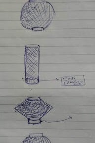
We need a structure which is diaphanous and should allow an ample amount of light. For this purpose, we will use the thread and make a structure. I did a small design sketch before starting and finalised on cylindrical table lamp design.
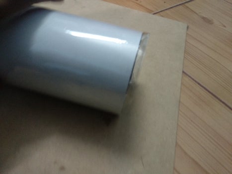
For this, we will first put that thick paper sheet inside the plastic envelope and pin it using staplers to make a cylinder.
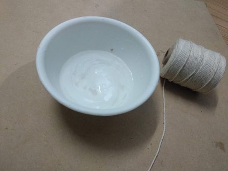
Prepare a solution of paper glue and water in the ratio of 1:4 respectively. Mix well until the glue gets dissolved in water. Dip the stings in this solution and wrap it around the paper cylinder in a random fashion. Once you wind it for the required length you can cut the thread and leave it aside for drying.
Step 2: Step 2: Stand
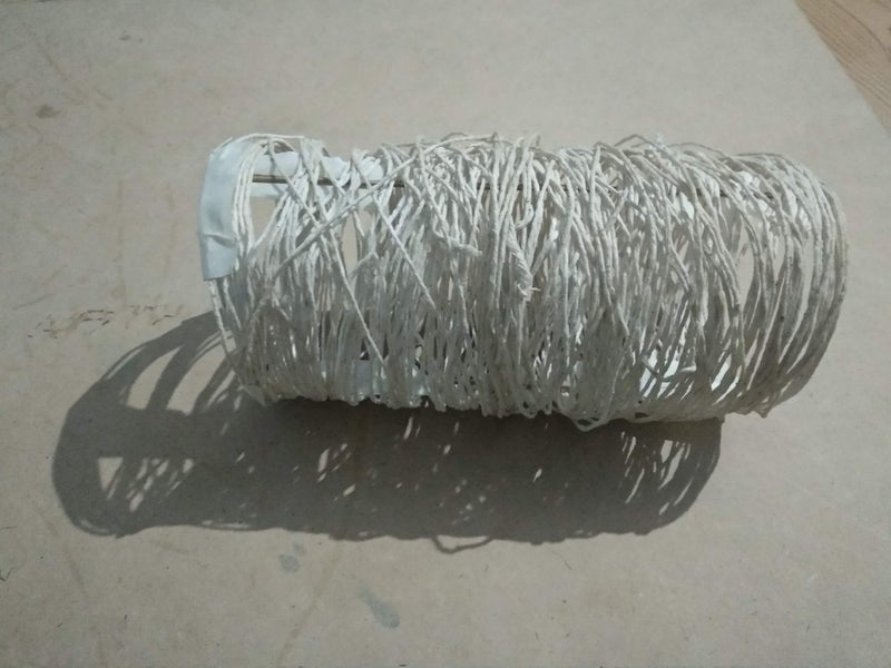
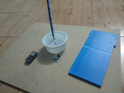
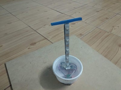
After 5 hours of drying the diaphanous thread skeleton will look like this. We need a stand to hold this and our lights. So I chose corrugated plastic sheets. Using the cutter blade I had cut a thin strip of that sheet and made it as central support. My neopixel LED had sticky tape behind so I stuck it to my central support and pierced a hole in the food container to make it as a stand. This how my setup looks like.
Step 3: Connecting Everything
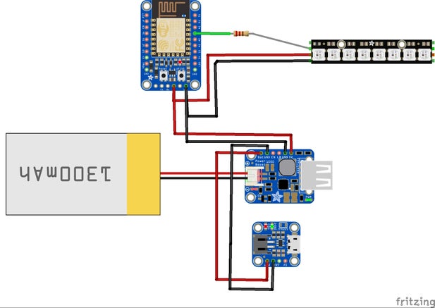
The connection is very simple. I'm using an ESP8266 based board for wifi and to drive neopixel LEDs.
The connection is as follows:
D2 (GPIO 4) of Node MCU to Data in pin of Neopixel LED through a 330 Ohm resistor.
Vin to 5V from boost circuit.
GND to GND of the boost circuit.
Neopixel LED VCC to 5V, GND to GND.
TP4056 charging circuit to battery +ve and negative terminal.
Battery terminals to inputs of boost circuit via optional switch to control output.
I wanted my lamp to work even when the power is not there, so I'm attaching a rechargeable Li-ion battery which is having a capacity of 2200mAh.
Total running time on battery:
Average current consumption by LED is around 45mA any colour other than white with medium brightness. for white with full brightness it is around 60mA.
Running time = 2200/(45*10) = 5 hours. (10 LEDs )
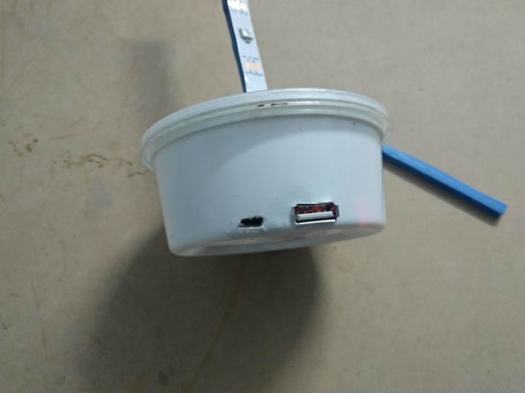
Also, the boost circuit can provide 5V output 1A through its USB 2.0 Female port this can also be used as an emergency power bank for smartphone and other devices compatible with 5V.
Step 4: Coding and Creating a Project in Blynk Application.
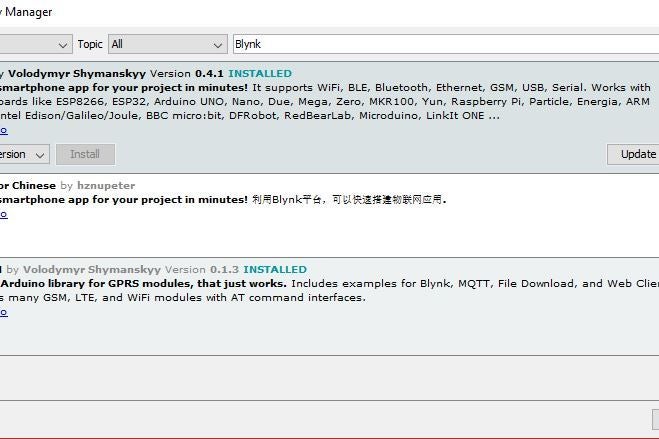
There is one very good application called blynk which allows us to rapidly interface IoT devices and test them out. Now signup for blynk and create a new project called lamp. Install blynk library from arduino library manager :
Sketch >> Include library >> Library Manager
Now open the Blynk application and navigate your project lamp.
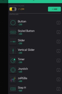
Through the sidebar use the zeRGBa module and import it to your workplace.
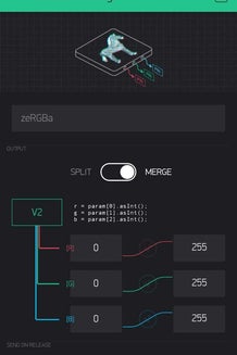
Now click on the zeRGBa and select the options as shown in the image.
Now click on NUT icon which is settings to select the device. Select device as ESP8266. then save it. Get the authentification token of the project over your registered email by clicking email all in settings.
In the Arduino code add this authentification code, wifi credentials and upload it.
Blynk.begin("Auth Token", "Wifi SSID", "Wifi password");
(You might have to change parameters such as number of LEDs and pin etc.)
#define PIN D2 //GPIO4
#define NUMPIXELS 10 // 10 LEDs are connected
Step 5: Step 5: Connect to Internet and Viola
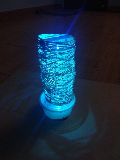
Now after programming the node mcu device it will automatically connect to blynk server and you will see that your device is online in the 2nd icon of the top right corner. now you can move that curser ball on zeRGBa to get required colour on the lamp. Hence our mummified Wifi lamp is cool and awesome with all possible colours. You can also make different designs of that outer thread skeleton like a ball etc.
Features:
1. Wifi Controllable
2. Multicolour
3. Eco-friendly and made of waste materials
4. Has a backup of 5 hours approximately.
5. Has a power bank option.


 Mummy_Lamp.ino
Top Comments