element14 Community
element14 Community
    Register Log In
  • Site
  • Search
  • Log In Register
  • About Us
  • Community Hub
    Community Hub
    • What's New on element14
    • Feedback and Support
    • Benefits of Membership
    • Personal Blogs
    • Members Area
    • Achievement Levels
  • Learn
    Learn
    • Ask an Expert
    • eBooks
    • element14 presents
    • Learning Center
    • Tech Spotlight
    • STEM Academy
    • Webinars, Training and Events
    • Learning Groups
  • Technologies
    Technologies
    • 3D Printing
    • FPGA
    • Industrial Automation
    • Internet of Things
    • Power & Energy
    • Sensors
    • Technology Groups
  • Challenges & Projects
    Challenges & Projects
    • Design Challenges
    • element14 presents Projects
    • Project14
    • Arduino Projects
    • Raspberry Pi Projects
    • Project Groups
  • Products
    Products
    • Arduino
    • Avnet Boards Community
    • Dev Tools
    • Manufacturers
    • Multicomp Pro
    • Product Groups
    • Raspberry Pi
    • RoadTests & Reviews
  • Store
    Store
    • Visit Your Store
    • Choose another store...
      • Europe
      •  Austria (German)
      •  Belgium (Dutch, French)
      •  Bulgaria (Bulgarian)
      •  Czech Republic (Czech)
      •  Denmark (Danish)
      •  Estonia (Estonian)
      •  Finland (Finnish)
      •  France (French)
      •  Germany (German)
      •  Hungary (Hungarian)
      •  Ireland
      •  Israel
      •  Italy (Italian)
      •  Latvia (Latvian)
      •  
      •  Lithuania (Lithuanian)
      •  Netherlands (Dutch)
      •  Norway (Norwegian)
      •  Poland (Polish)
      •  Portugal (Portuguese)
      •  Romania (Romanian)
      •  Russia (Russian)
      •  Slovakia (Slovak)
      •  Slovenia (Slovenian)
      •  Spain (Spanish)
      •  Sweden (Swedish)
      •  Switzerland(German, French)
      •  Turkey (Turkish)
      •  United Kingdom
      • Asia Pacific
      •  Australia
      •  China
      •  Hong Kong
      •  India
      •  Korea (Korean)
      •  Malaysia
      •  New Zealand
      •  Philippines
      •  Singapore
      •  Taiwan
      •  Thailand (Thai)
      • Americas
      •  Brazil (Portuguese)
      •  Canada
      •  Mexico (Spanish)
      •  United States
      Can't find the country/region you're looking for? Visit our export site or find a local distributor.
  • Translate
  • Profile
  • Settings
555 Timer Madness
  • Challenges & Projects
  • Project14
  • 555 Timer Madness
  • More
  • Cancel
555 Timer Madness
Blog Dawn detector with hysteresis using 555
  • Blog
  • Forum
  • Documents
  • Events
  • Leaderboard
  • Polls
  • Files
  • Members
  • Mentions
  • Sub-Groups
  • Tags
  • More
  • Cancel
  • New
Join 555 Timer Madness to participate - click to join for free!
  • Share
  • More
  • Cancel
Group Actions
  • Group RSS
  • More
  • Cancel
Engagement
  • Author Author: JWx
  • Date Created: 17 Oct 2022 9:06 AM Date Created
  • Views 1378 views
  • Likes 12 likes
  • Comments 1 comment
Related
Recommended

Dawn detector with hysteresis using 555

JWx
JWx
17 Oct 2022

As most applications of 555 are generators/timing circuits, lets try something different.

As we can see from block diagram of 555, we have two comparators (detecting voltages greater than 2/3 of Vcc or lower than 1/3 of Vcc) and R-S flip-flop.

What we can do with that? Some sort of switch with hysteresis of course! It can be thermostat or - as in this sample circuit - a dusk/dawn detector (that can be used for switching on building's external lights after sunset).

Proposed circuit's diagram is as below:

image

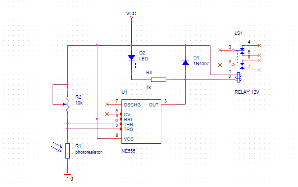
When there is enough light, R1 has low resistance, driving Threshold and Trigger voltages below 1/3 of Vcc, which sets output voltage to high level and turns off the relay.

When the light intensity lowers, output stays high until Threshold/Trigger voltage exceeds 2/3 of Vcc. At this point output voltage of 555 switches to low level, activating the relay.

Difference between 1/3 of Vcc and 2/3 of Vcc  is a circuit's hysteresis window, preventing oscillations when light intensity changes near switching point.

Usage of 555 in this circuit is justified by the fact that it can directly drive relay's coil, unlike some schmitt-trigger logic gates that we could use instead. Large supply voltage range of 555 means that it can be powered directly from the same power supply as the relay, reducing component count.

R2 can be used to set  a detection level and relay model have to be selected to have coil current below 200mA to not overload 555's output stage.

If somebody wants to  convert this circuit into a thermostat, one can replace photoresistor with NTC thermistor and maybe modify R2 value...

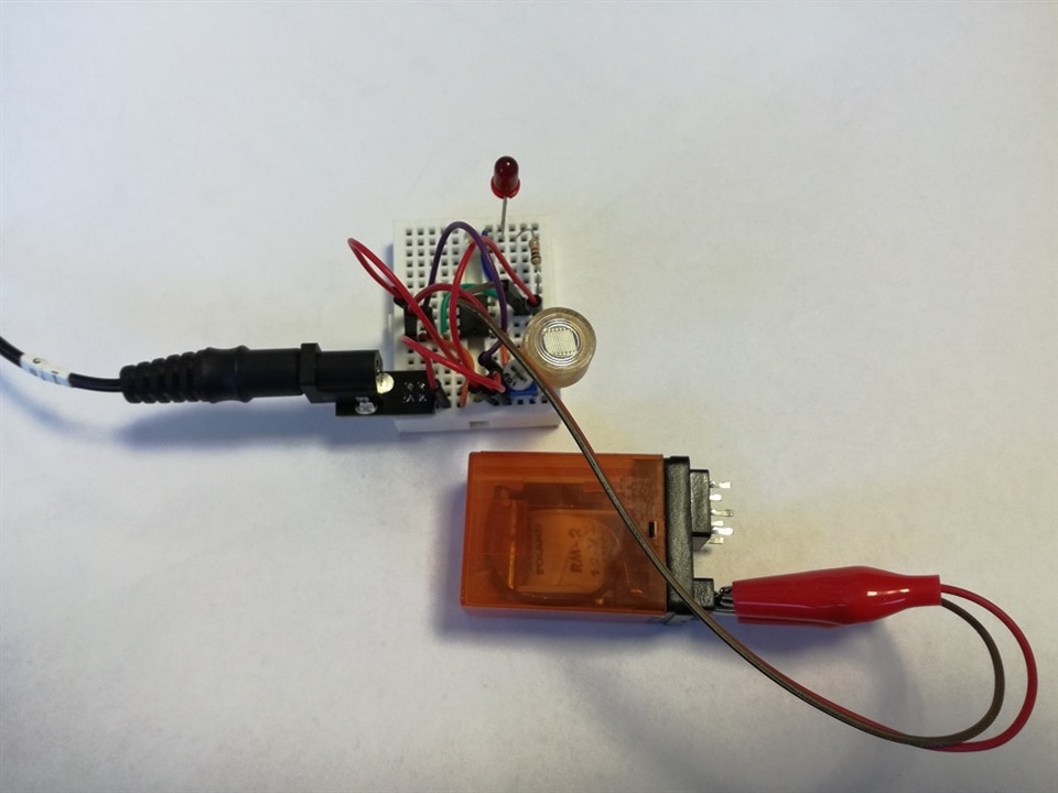
Photo below shows breadboard implementation of this circuit.

image

  • Sign in to reply
  • JWx
    JWx over 2 years ago

    Including mandatory video proof of work

    You don't have permission to edit metadata of this video.
    Edit media
    x
    image
    Upload Preview
    image

    • Cancel
    • Vote Up 0 Vote Down
    • Sign in to reply
    • More
    • Cancel
element14 Community

element14 is the first online community specifically for engineers. Connect with your peers and get expert answers to your questions.

  • Members
  • Learn
  • Technologies
  • Challenges & Projects
  • Products
  • Store
  • About Us
  • Feedback & Support
  • FAQs
  • Terms of Use
  • Privacy Policy
  • Legal and Copyright Notices
  • Sitemap
  • Cookies

An Avnet Company © 2025 Premier Farnell Limited. All Rights Reserved.

Premier Farnell Ltd, registered in England and Wales (no 00876412), registered office: Farnell House, Forge Lane, Leeds LS12 2NE.

ICP 备案号 10220084.

Follow element14

  • X
  • Facebook
  • linkedin
  • YouTube