As most applications of 555 are generators/timing circuits, lets try something different.
As we can see from block diagram of 555, we have two comparators (detecting voltages greater than 2/3 of Vcc or lower than 1/3 of Vcc) and R-S flip-flop.
What we can do with that? Some sort of switch with hysteresis of course! It can be thermostat or - as in this sample circuit - a dusk/dawn detector (that can be used for switching on building's external lights after sunset).
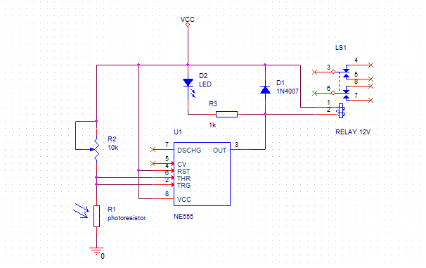
Proposed circuit's diagram is as below:

When there is enough light, R1 has low resistance, driving Threshold and Trigger voltages below 1/3 of Vcc, which sets output voltage to high level and turns off the relay.
When the light intensity lowers, output stays high until Threshold/Trigger voltage exceeds 2/3 of Vcc. At this point output voltage of 555 switches to low level, activating the relay.
Difference between 1/3 of Vcc and 2/3 of Vcc is a circuit's hysteresis window, preventing oscillations when light intensity changes near switching point.
Usage of 555 in this circuit is justified by the fact that it can directly drive relay's coil, unlike some schmitt-trigger logic gates that we could use instead. Large supply voltage range of 555 means that it can be powered directly from the same power supply as the relay, reducing component count.
R2 can be used to set a detection level and relay model have to be selected to have coil current below 200mA to not overload 555's output stage.
If somebody wants to convert this circuit into a thermostat, one can replace photoresistor with NTC thermistor and maybe modify R2 value...
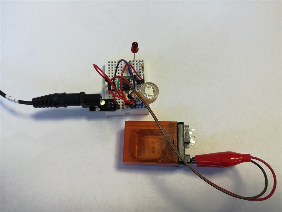
Photo below shows breadboard implementation of this circuit.


-

JWx
-
Cancel
-
Vote Up
0
Vote Down
-
-
Sign in to reply
-
More
-
Cancel
Comment-

JWx
-
Cancel
-
Vote Up
0
Vote Down
-
-
Sign in to reply
-
More
-
Cancel
Children