


Contents-
Blog 1: How to use 555 timer IC for sensor interfacing: Converting the sensor output to frequency
Blog 2: How to use 555 timer IC for sensor interfacing: Part-2 Wireless transmission
This is my project entry for the 555 timer madness project14. 555 timers ICs are quite popular in many hobby projects. My first 555 timer project was a LED flasher in the year 2010. 555 timers can be operated in two modes - the astable mode and the monostable mode. In my project I'll be using the timer IC in astable mode.
While I was experimenting with the thermistors in the last experimenting with thermistors challenge, I wanted to transmit the thermistor's temperature reading (change is resistance) over a long distance using some wireless technology. However, since the thermistor circuits use a voltage divider to read the DC voltage change due to the change in its resistance with respect to the temperature, this DC output cannot be transmitted wirelessly. One option to tackle this was to use a microcontroller and an ADC, where one would sample the voltage using the ADC, convert it into a digital value and then transmit it using BLE, RF, Wi-Fi, etc. However, this method is quite expensive, resource hungry and power consuming. Just to transmit a simple DC voltage value, we need huge resources like MCU and ADC. I wanted something simple and analog in nature. Something that won't consume much of power and something that uses basic principles of electronics.
So, I had an idea in my mind. What if somehow, I can convert the thermistor response into a time varying waveform? Because for wireless transmission all you need is a time varying signal that can be modulated using a carrier be it analog modulation or digital modulation, we always need the data to be transmitted in a time varying form.
Hence, there was a need to somehow convert this DC voltage into a time varying voltage waveform. One solution to this is use an opamp based voltage to frequency converter. Another method is to use a 555 timer IC in astable mode and replace one of the resistors with a thermistor or any other sensor that produces change in resistance in response to stimulus.
But does this method work? Let's find out.
Below is the circuit for 555 timer in astable mode -

Here, the 555 timer works as an oscillator where the output frequency is set by R1, R2 and C. The formula for output freq.

So, any change in R1, R2 or C will affect the output frequency.
Here, I replaced R1 with a thermistor. Now whenever, the thermistor will change its resistance with respect to the change in temperature and this will change the output frequency of the 555 timer. Which means that the thermistors output is successfully converted into a time varying waveform.
I quickly made a circuit on the breadboard and tested it. Guess what? It works!!
Here's my overall setup -
I'm using the CMOS 555 timer IC (TLC555) with R1 replaced with a thermistor from the thermistor's kit I received as a part of the experimenting with thermistor's challenge. R2 is fixed at 5.5kOhms and C is 0.01uF.
I'm using a Keysight E36312A bench power supply set at 5V to power the circuit.
A BK Precision 2707B for measuring the frequency of the output (I don't have an oscilloscope)
And finally, a piezo disc to hear the frequency output in audio form.
This is my overall setup -
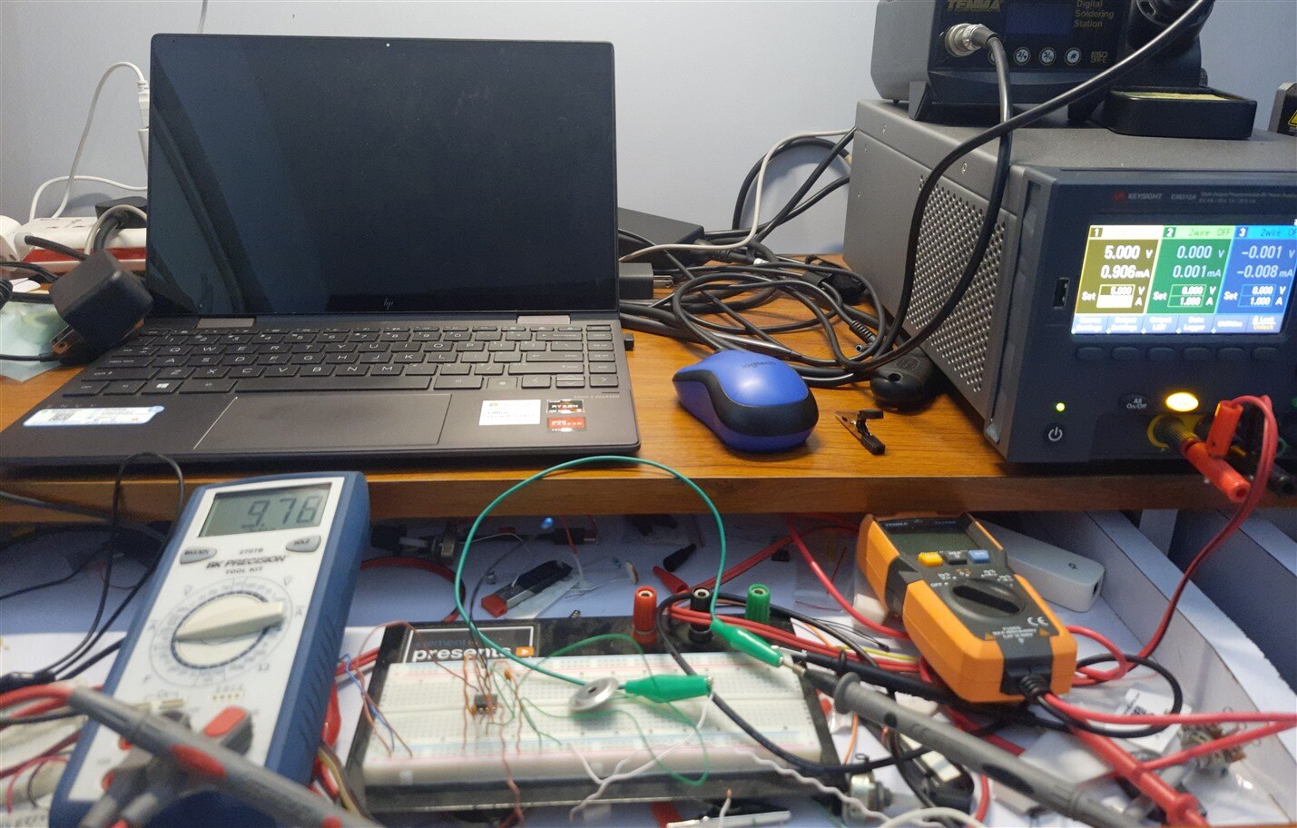
A closeup view in power off condition -

Now, at ambient temperature when I power it on, the current frequency output is 9.7kHz. As mentioned above, R1 is thermistor with resistance of 3.7K at ambient temp., R2 is 5.5K and C is 0.01uF, this gives an output freq. of 9.7KHz. Which matches with the experimental value.
Resistance of thermistor at ambient temperature -

Output freq. at ambient temperature-

When I touch the thermistor with my hands the thermistor resistance will drop, and the output freq. should increase. The same is observed on the breadboard circuit, an output freq. of 10.57kHz.

For further experimentation, I heated up my soldering iron and touched the tip of the iron with the thermistor, and the frequency increased further to 13.99 kHz.

Here's the video for the listening to the piezo buzzer output. It can be observed that as soon I touch the thermistor with the soldering iron, the pitch of the piezo buzzer goes higher and the frequency reading on the DMM also increases. When I remove the soldering iron, the frequency starts decreasing.
Since I'm using the CMOS version of the 555, the output can go as high as 2MHz!
*A high pitch sound warning. Could be irritating to hear*
Now the next aim is to transmit this output frequency signal over a wireless channel so that we can read the sensor output at a far-off distance. In the 2nd part of this project, I will demonstrate how I was able to transmit this output frequency using amplitude shift keying (ASK) module and find a correlation between the output frequency of 555 and the temperature reading of the thermistor.

