In my last blog How to use 555 timer IC for sensor interfacing: Converting the sensor output to frequency, I showed how to convert the themistor resistance into frequency using 555 timer IC so that it can be transmitted wirelessly.
In this blog, I will continue the project, where I will transmit the frequency wirelessly. But before doing that, let's do some calculations to get a relation between the temperature of the thermistor and the frequency output of the 555 timer.
I tried taking the reading again today since the last blog was posted about a week ago.
At ambient temperature, the resistance reading of the thermistor is around 3.8 kOhms.
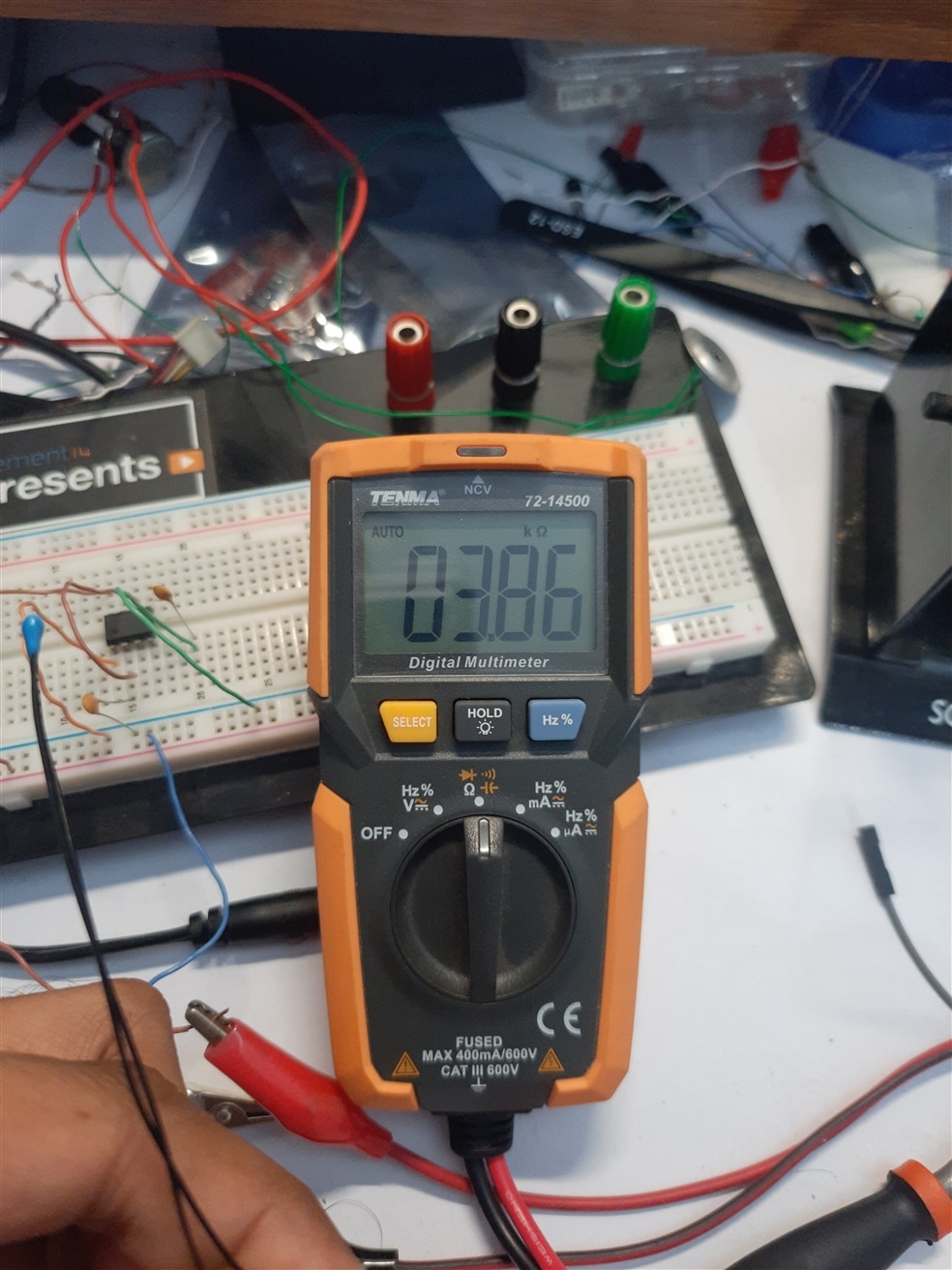

Which gives us a temperature of slightly less than30 deg C. I took out my Multicomp Pro Temperature data logger and it reads a temperature of 29 deg C.

Since, the above table gives a good enough resolution of 5 deg C which is okay for a simple project, I'm not going in detail with the Steinhart eqn. to estimate the resistance of thermistor and the temperature. Instead, I made a simple table that gives the output freq. of 555 timers with respect to the thermistor resistance and temperature and plotted the values of resistance and frequency with respect to the temperature. 
An interesting thing that I noticed after this was that the freq. output is almost linear with respect to the temperature. Which makes it easier to calculate the freq. output at any given temperature due to the constant slope of the curve.
Now it's time to transmit the freq. wirelessly.
I will be using these ASK modules that transmit at 433 MHz.
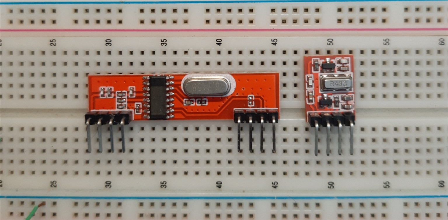
Each module has a pair of Tx and Rx. The Tx has 4 pins, Vcc, Gnd, Data and Antenna. The data pin can take digital data directly. And since the output of 555 timer is a square wave this can be interpreted as a digital signal and can be directly fed to the Tx. The Tx will then use the frequency output from 555 timer as a modulating signal and ASK modulate the 433 MHz carrier.
On the Rx side, there are 4 pins (note out of 8 pins most are repetitive pins like Gnd). The 4 pins are - Vcc, Gnd, Data and Antenna. Here the data pin gives us the demodulated data received at the receiver in baseband form (means the same data that was transmitted).
Now in theory this should work, but in practical will it work? Let's find out -
This simple block diagram shows the connection of the modules with the 555.

I quickly assembled the circuit on two separate breadboards. One for the 555 timer +Tx and the other breadboard for the Rx.
I have also used two independent power sources. So as to reduce any chance of data being coupled through the power lines if Tx and Rx are both powered with same source.
Here are the results -
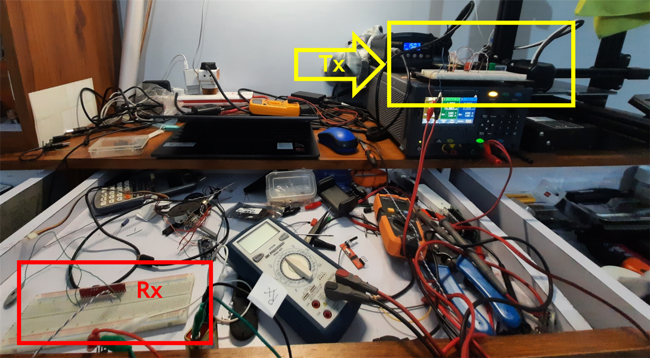
The overall setup with Tx and Rx kept at a distance
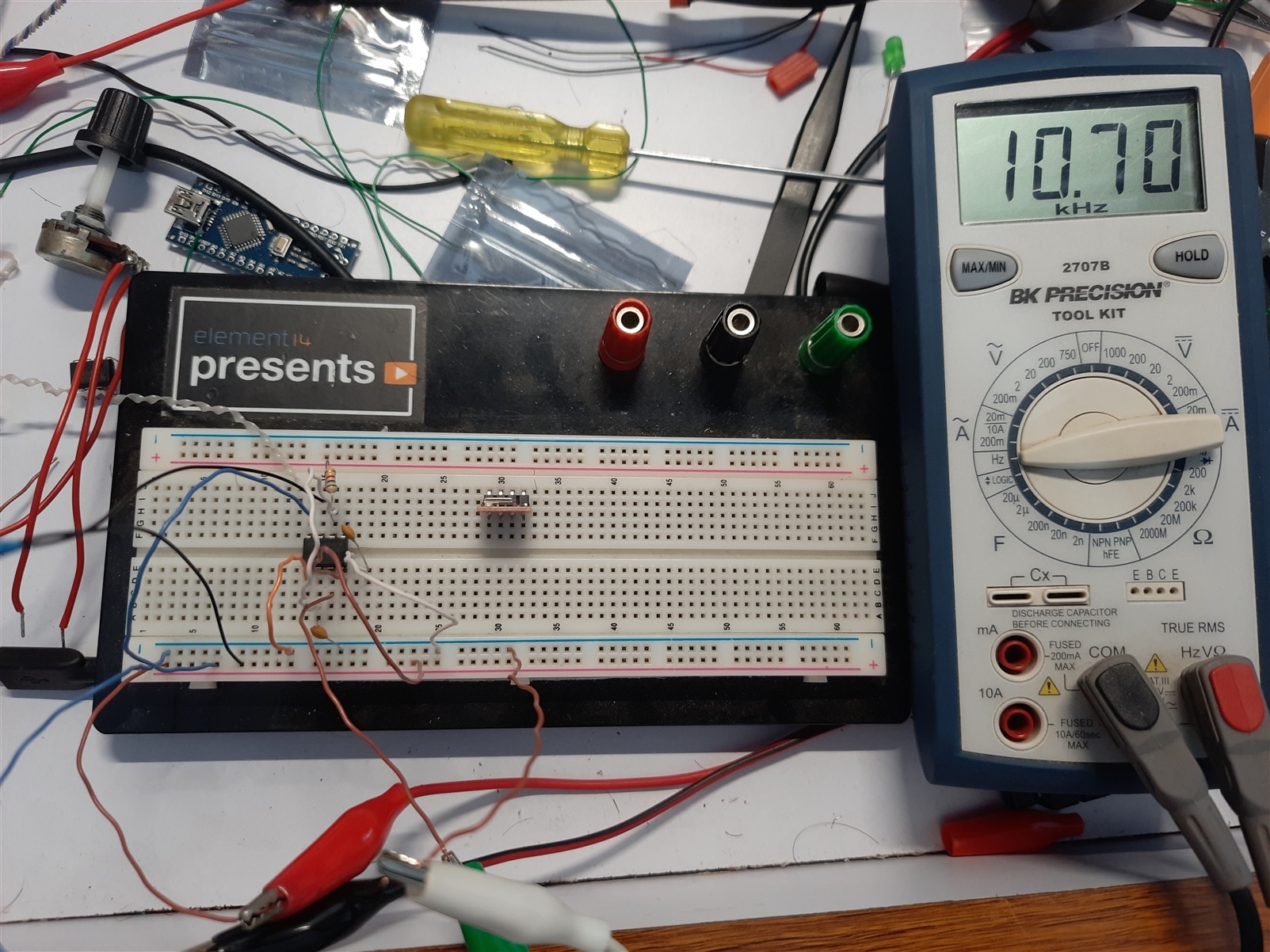
First, I took the frequency reading at the Tx, it was 10.7kHz.
Then I checked the frequency reading at the Rx, it was almost similar to the Tx 10.62kHz
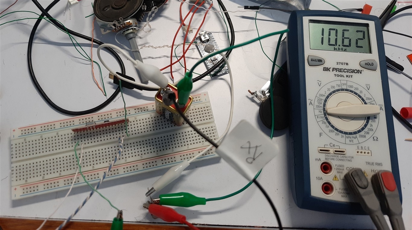
This shows that the module was able to transmit the output of 555 timer successfully.
For further results, I have recorded these two videos. First video shows the audio signal at Rx. Initially the 555 timer and Tx are powered off, and at Rx we can hear noise. As soon as I power on the 555 timer and Tx, we can hear some audio signal at the Rx data pin which is connected to a piezo buzzer.
Further, I heat up the thermistor bead and it can be seen that the audio signal's frequency goes very high that it is beyond the bandwidth of my microphone, so it doesn't record it well.
Next, I recorded another video that shows frequency measurement at the data pin of the Rx. In the video it can be seen that the initial frequency is around 10.65kHz which is the same as measured at the Tx side. Now again, when I heat the thermistor bead, the frequency starts increasing.
Conclusion-
So, in conclusion, the thermistor resistance is converted to frequency using a 555 timer IC so that it can be transmitted wirelessly. This conversion of resistance to frequency also helped us linearize the thermistor response.
Then the frequency output of 555 timer is fed to a transmitter module. On the other side, a Rx module is used to receive the demodulated signal. It can be seen that the results are almost consistent with the theory, and it is possible to transmit the output of 555 directly using the RF module. All the results measured independenty at the Tx side and Rx side match with each other.
I had lot of fun building and troubleshooting these experiments around 555 timer IC.
