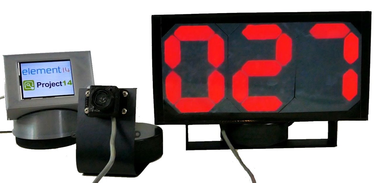
The Pico Parker displays the distance from the Maxbotix ultrasonic transducer to the nearest object in cm - in this case the nearest object will be a car and the distance will be the distance to the end of the garage as it tries to park..
Intro
This blog describes my attempt to make a vehicle parking aid. Our garage is a very tight fit for a car, requiring parking accuracy of a few inches. This project addresses the issue of parking close to the end of the garage without bumping into the anything. There are other ways to achieve this goal, but I also want to explore how to make a large seven segment LED display with well formed segments.
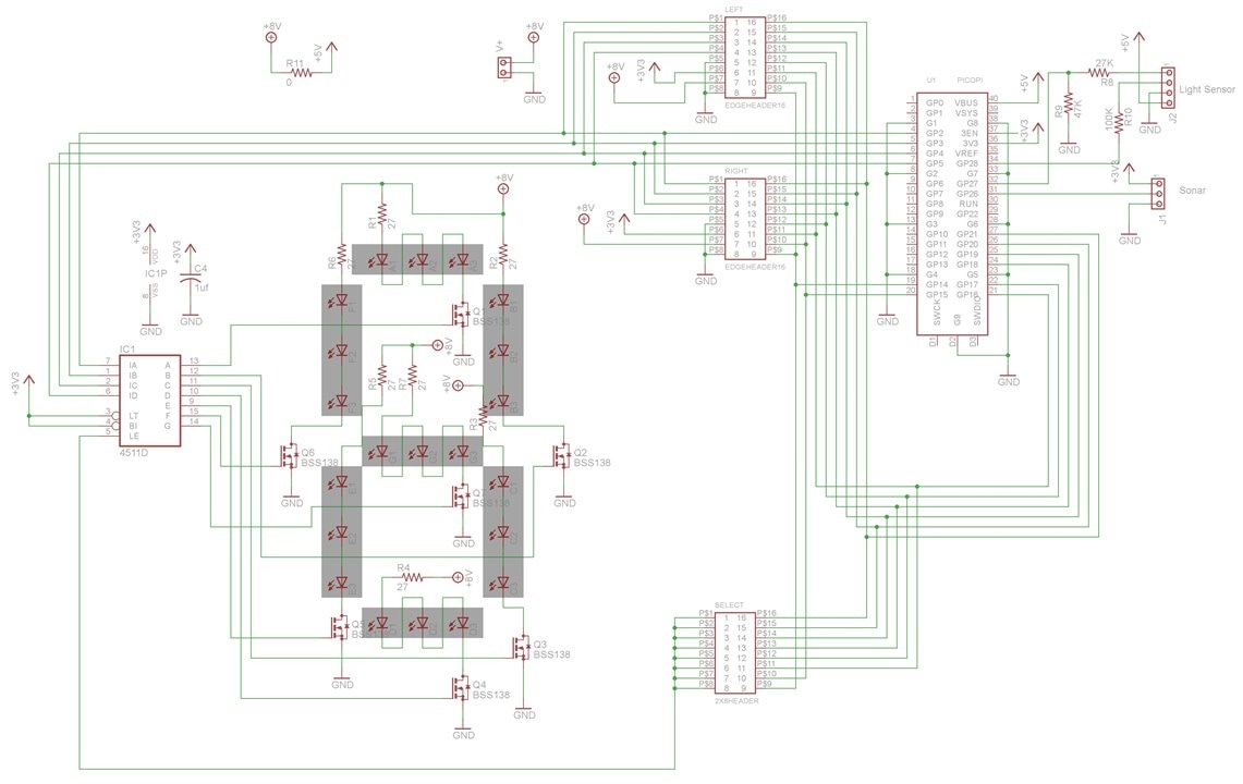
There are other objectives as well. Since the project is going to involve video blogging, I want to design an LED display that can be videoed without any ugly and distracting blinking or partial displays due to multiplexing of LEDs, where each LED spends a significant portion of the time in the off condition. The eye doesn't notice LEDs blinking off if their refresh rate is fast, but the camera easily catches LEDs in the off condition and it makes for poor presentation of a project. To achieve this, the LEDs will not be multiplexed, but the BCD digits will use a bus to keep the number of MCU pins to a minimum. The BCD nibbles will be latched, eliminating LED flicker.
The display needs to be large so it can easily be read at 3 meters, but the PCB shop I use has a price break for PCBs under 10 cm, so this dictates the digits will be about 10 cm high. This height dictates that 3 digits will be wider than 10 cm, so each digit needs to be on a separate PCB. This does not affect costs, because the minimum number of PCBs is 10. The cost of 10 PCBs is $5. The following video describes how these PCBs implement a 3 digit seven segment display.
Pico Parker Development
Pico Parker DEMO
The next video shows my better half parking with the display. It is a good test of a project if someone else can figure out how to use it.
The engine sounds are actually just sound effects - her car is actually pretty silent.
Schematic

Firmware
// Pico Parker
// Ultrasonic range display
// Doug Wong
// 2022-06-19

const int ledPin =  LED_BUILTIN;// the number of the LED pin
int ledState = LOW;             // ledState used to set the LED

//BCD Pins
int BCD1 = 2; //BCD Bit 0
int BCD2 = 3; //BCD Bit 1
int BCD3 = 4; //BCD Bit 2
int BCD4 = 5; //BCD Bit 3

//BCD Selects
int S1 = 14;  //BCD digit select 1
int S2 = 15;  //BCD digit select 2
int S3 = 16;  //BCD digit select 3
int S4 = 17;  //BCD digit select 4

int n=0;        //Setting initial value of sonar reading n to 0
float sn;       //need a bigger number than an integer to scale sonar readings
int d1, d2, d3; // digits
int digit;      //digit number
int sonar, cm, light;
int SonarPin = 26;


void setup()
{

// Serial.begin(9600);

pinMode(ledPin, OUTPUT);

pinMode(2,OUTPUT);   //BCD Bit 0
pinMode(3,OUTPUT);   //BCD Bit 1
pinMode(4,OUTPUT);   //BCD Bit 2
pinMode(5,OUTPUT);   //BCD Bit 3
pinMode(14,OUTPUT);  //BCD digit select 1
pinMode(15,OUTPUT);  //BCD digit select 2
pinMode(16,OUTPUT);  //BCD digit select 3
pinMode(17,OUTPUT);  //BCD digit select 4
pinMode(18,OUTPUT);  //BCD digit select 5
pinMode(19,OUTPUT);  //BCD digit select 6
pinMode(20,OUTPUT);  //BCD digit select 7
pinMode(21,OUTPUT);  //BCD digit select 8

pinMode(26,INPUT);    //sonar - analog
pinMode(27,INPUT);    //digital light
pinMode(28,INPUT);    //analog light
}

void loop()
{
sonar =0;
for (int i = 1; i < 11; i++)
{
  sonar = analogRead(SonarPin) + sonar;
  delay (6);
}
sonar = sonar / 10;
sn = sonar * 240/170 - 25;    // scale sonar  reading to cm

    if (ledState == LOW) {
      ledState = HIGH;
    } else {
      ledState = LOW;
    }
    digitalWrite(ledPin, ledState);
    delay (200);

// Serial.print(n);
 if (sn > 999)
 {
  n = 999;
 }
  else
  {
    n = int (sn);
  }

 d3 = n / 100;      //extract MSD
 n = n - d3 * 100;
 d2 = n/ 10;        // extract 2nd digit
 n = n - d2 *10;
 d1 = n;            //grab LSD
// Serial.print ("  ");
// Serial.print(d3);
// Serial.print ("  ");
// Serial.print(d2);
// Serial.print ("  ");
// Serial.print(d1);
// Serial.println();

 disp(d1);                //output digit 1 in BCD
 digitalWrite(S1, LOW);   //strobe digit 1
 delay(2);                //stay low for 1 ms
 digitalWrite(S1, HIGH);  //latch digit 1
 disp(d2);                //output digit 2 in BCD
 digitalWrite(S2, LOW);   //strobe digit 2
 delay(2);                //stay low for 1 ms
 digitalWrite(S2, HIGH);  //latch digit 2
 disp(d3);                //output digit 3 in BCD
 digitalWrite(S3, LOW);   //strobe digit 3
 delay(2);                //stay low for 1 ms
 digitalWrite(S3, HIGH);  //latch digit 3

 delay(200);    // delay to dictate count rate

}
void disp(int num)
{
  if(num == 0)  //0000
  {
    digitalWrite(BCD1, LOW);
    digitalWrite(BCD2, LOW);
    digitalWrite(BCD3, LOW);
    digitalWrite(BCD4, LOW);
  }
  if(num == 1)  //0001
  {
    digitalWrite(BCD1, HIGH);
    digitalWrite(BCD2, LOW);
    digitalWrite(BCD3, LOW);
    digitalWrite(BCD4, LOW);
  }
  if(num == 2)  //0010
  {
    digitalWrite(BCD1, LOW);//0
    digitalWrite(BCD2, HIGH);//1
    digitalWrite(BCD3, LOW);//0
    digitalWrite(BCD4, LOW);//0
  }
  if(num == 3)  //0011
  {
    digitalWrite(BCD1, HIGH);//1
    digitalWrite(BCD2, HIGH);//1
    digitalWrite(BCD3, LOW);//0
    digitalWrite(BCD4, LOW);//0
  }
  if(num == 4)  //0100
  {
    digitalWrite(BCD1, LOW);//0
    digitalWrite(BCD2, LOW);//0
    digitalWrite(BCD3, HIGH);//1
    digitalWrite(BCD4, LOW);//0
  }
  if(num == 5)  //0101
  {
    digitalWrite(BCD1, HIGH);//1
    digitalWrite(BCD2, LOW);//0
    digitalWrite(BCD3, HIGH);//1
    digitalWrite(BCD4, LOW);//0
  }
  if(num == 6)  //0110
  {
    digitalWrite(BCD1, LOW);//0
    digitalWrite(BCD2, HIGH);//1
    digitalWrite(BCD3, HIGH);//1
    digitalWrite(BCD4, LOW);//0
  }
  if(num == 7) //0111
  {
    digitalWrite(BCD1, HIGH);//1
    digitalWrite(BCD2, HIGH);//1
    digitalWrite(BCD3, HIGH);//1
    digitalWrite(BCD4, LOW);//0
  }
  if(num == 8) //1000
  {
    digitalWrite(BCD1, LOW);//0
    digitalWrite(BCD2, LOW);//0
    digitalWrite(BCD3, LOW);//0
    digitalWrite(BCD4, HIGH);//1
  }
  if(num == 9)  //1001
  {
    digitalWrite(BCD1, HIGH);//1
    digitalWrite(BCD2, LOW);//0
    digitalWrite(BCD3, LOW);//0
    digitalWrite(BCD4, HIGH);//1
  }
  delay (2);
}
BoM
| Item | Cost |
| Pico | $ 4.00 |
| LEDs | $ 2.00 |
| electronic components | $ 3.00 |
| 3 PCBs | $ 1.50 |
| connectors | $ 1.00 |
| plastic case | $ 2.00 |
| voltage booster | $ 2.00 |
| cables | $ 2.00 |
| USB power | $ 3.00 |
| SubTotal | $ 20.50 |
| Maxbotix EZ0 | $ 34.00 |
| Total | $ 54.50 |
Summary & Discussion
This project involved schematic and PCB design, mechanical design, 3D printing of the case, optical design and firmware design, so it is a nice multi-disciplinary project. Achieving good optical performance was one of the most difficult aspects of the design. The costs were kept reasonable by using a Raspberry Pi Pico and adhering to low cost PCB constraints - the whole display system cost less than the sensor. It is nice when you can finish the project off and make it look like a product you might buy. I am happy with the results - the display looks great and works well for its intended application.
Relevant Links
