The first season post is here.
Part III: the smart display
Let me introduce you the Smart Display, built on the Stranger Segs platform!
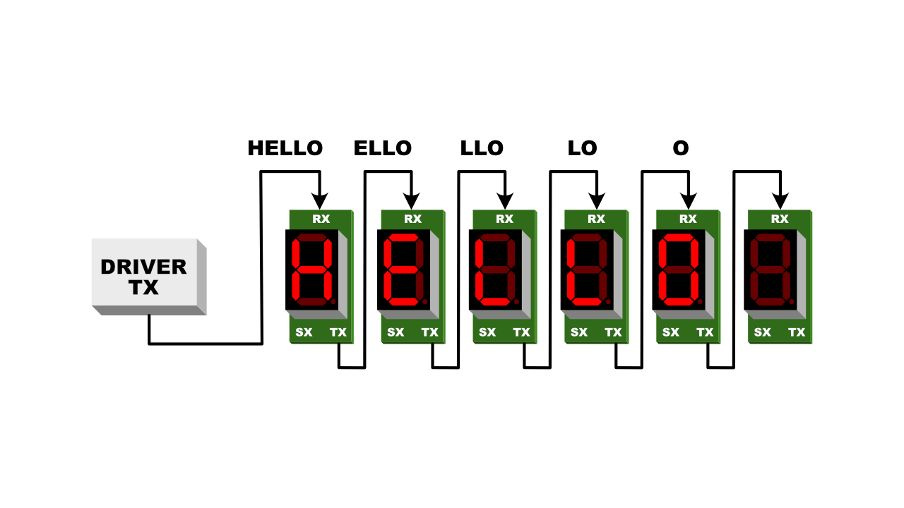
It’s basically an application to display a character from a message transmitted by a driver application (a stream of ASCII characters through a UART). Modules are daisy-chained together through their UARTs. Each module does two things:
- it gets the first character of the message and puts it on display.
- it forwards the remaining characters of the message to the next module in the chain.
When the message is long enough, each module in the chain receives a character.

This application is nothing new nor revolutionary. People smarter than me have already developed variations of this application using everything from a LED controller to a full-featured MCU. Follow this link for an example. There are lots of implementations out there.
My variation adds something strange in two ways.
First, the protocol is a plain stream of ASCII characters. This means that to drive the composite display suffices to echo some characters to a device file (at least on a POSIX platform). Of course, if you take the time to write a proper driver application, some interesting animations effects may be achieved.
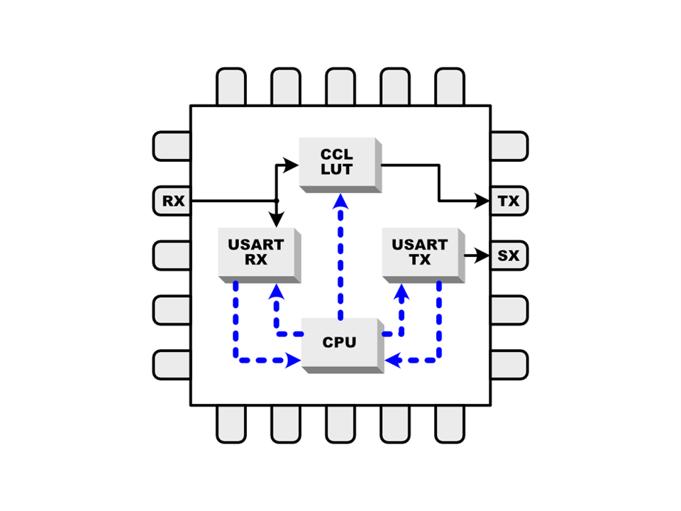
Second, I don’t use the TX unit of the UART to forward the message but I use instead the output of the LUT0 from the CCL peripheral. This means that I obtain a near-zero-latency forward of the message and that the TX unit is free for other weird project ideas. More on this later :-)
The CCL LUT and the message forward
The motivation to use an avrtiny in this project was exactly to play with the CCL.
The idea is to use the LUT0 of the CCL to replicate the logic state of the RX pin (one of the LUT0 inputs) to another pin (the LUT0 output). Obviously, the LUT0 output must be fixed to 1 (the USART idle state) until the first character is received, then it shall follow exactly the RX pin.

To obtain that, I used the alternate configuration of the USART pins to ensure that the RX pin is shared with any of the LUT0 inputs. This is not a problem, since multiple peripherals may read the state of a GPIO pin at the same time.
My first attempt was:
- configure the LUT to always output 1 (the idle state of the USART data line).
- when a character is received, the RXC IRQ is raised.
- In the RXC IRQ vector, reconfigure the LUT to follow its IN2 pin (the USART RX data line).
Once configured the input sources and the clocks, the LUT output depends on its truth table. At least in theory, the truth table may be changed with an atomic write to the TRUTH0 register (a byte). In practice, changing the output of the LUT on the fly is much more complicated. The sad truth is that to change anything in the CCL, you must disable everything (see the device errata sheet).
I worked around this limitation with a trick:
- The pin corresponding to the LUT output is configured to emit 1 (the idle state).
- The LUT is configured to always follow the RX pin.
- The CCL is enabled when I need the forward behaviour and disabled when I need the idle behaviour.
The trick works because the CCL takes over the pin state only when enabled.
To enable or disable the CCL, you toggle a bit. Easy and fast.
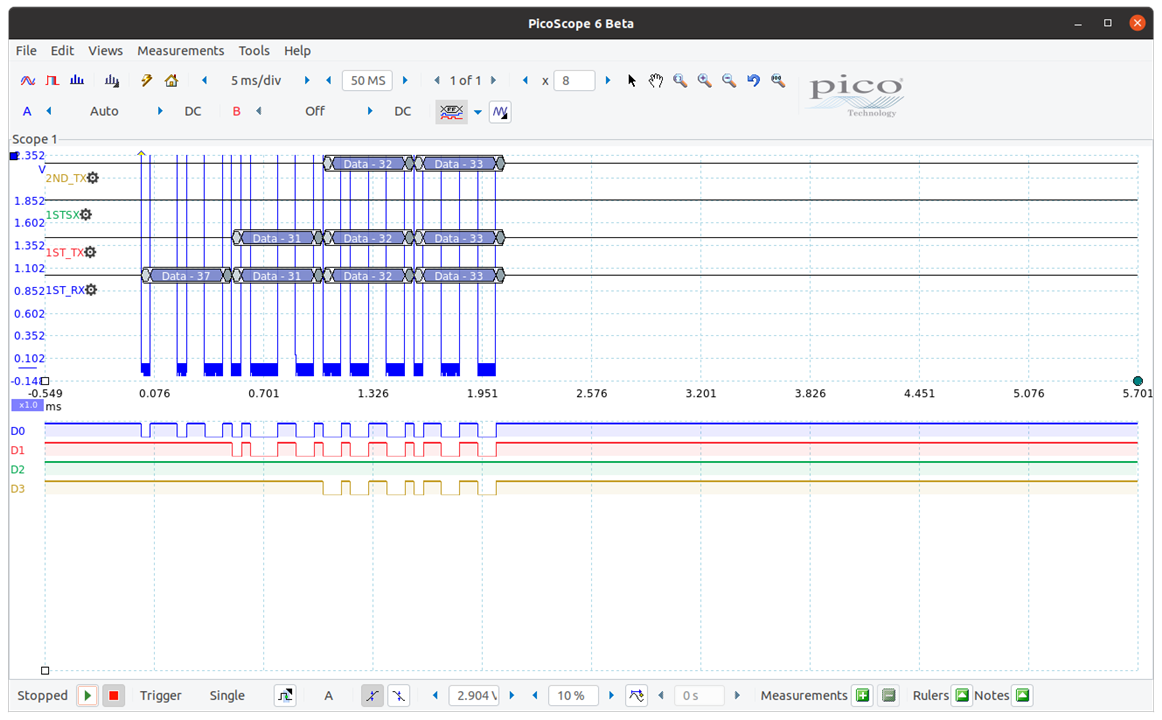
In the capture below, you may see the transmission of the four-character message “7123” across two modules daisy-chained through the TX port of the first.
The channels are:
- D0: 1st module RX
- D1: 1st module TX / 2nd module RX
- D2: 1st module SX (spare extension)
- D3: 2nd module TX

As you can see, the transition of the TX pin from the idle state to the forward state is unnoticeable and doesn’t change the timing of the message.
The communication protocol
Each message is composed of 8-bit character codes transmitted at 19200 bps, with no parity and 1 stop bit. A full character is transmitted in about 500 us. The message is considered terminated when the data line is idle for more than 50 ms. For applications with strict timing, this interval may be lowered.
The message unit is 8-bit wide even if the ASCII codes require only 7 bits. I use the 8th bit for an extra feature: when the bit 7 of a character is set, the dot of a display is turned on. The driver application knows that and when it detects a full stop following another character, it collapses both of them in a single byte.
The driver application
The driver that I used to test the application may do two things:
- send a plain message to a chain of modules, or
- animate a message with a scrolling effect mimicking the Times Square scrolling marquee.
The animation is obtained sending a sequence of messages, each long enough to be received by all modules, where each message contains the characters of the input string selected by a moving window large exactly as the number of modules chained together.
To connect the computer to the chain of modules, I used a battle-tested USB-to-serial adapter based on the ubiquitous FTDI chip. This had interesting consequences.
As I discovered observing weird behaviours in the adapter’s output, the OS has no idea when the USB-to-serial adapter has finished sending a message. This means that closing the serial port when the computer-side output has finished is a nice recipe to destroy the output on the wire. It seems that this feature is common to most USB-to-serial adapters so beware: always wait enough time to transmit buffered data before doing anything such as changing the termios options or closing the port.
The (not so) impressive demo
Disclaimer: I ordered two dozens of PCBs to build some modules and show the application in its full glory but it seems that the courier cannot deliver my parcel before I leave home to return to my daily job. I’ll be unable to build the modules until the end of June.
I’ll show you instead another breadboard prototype, this time with two modules chained together. Not really nice to see but it works. I’ll update this post with the intended video later.
Part IV: the weird, self-similar display
Do you remember that the USART TX port is free? What could we obtain when we send a pattern of characters across this port to another chain of display?
Let me introduce you the Self-Similar Display, built on the Stranger Segs platform!

Only a little deviation is needed to the firmware: when the FUSE0 pin (see the schematics) is 1, the application firmware does the usual job, but when the FUSE0 is 0 (the bridge is soldered), the application firmware uses the segment map of the character to display to compute the character to display (or not) and emit another message through the USART TX, as in the example below.

In the capture below, you may see the transmission of the two-character message “71” across two modules daisy-chained through the SX port of the first.
The channels are:
- D0: 1st module RX
- D1: 1st module TX / 2nd module RX
- D2: 1st module SX (spare extension)
- D3: 2nd module TX

As any self-similar data structure, this architecture is recursive: you may substitute each node with a self-similar display like that until the Universe runs out of 7-segment displays :-)
Further enhancements
Playing with 7-segment display was really amusing and I learned a lot regarding the new avrtiny cores.
The CCL was a bit disappointing but I’m sure that further explorations will reveal something interesting to try.
There is space for one more application. Since the driver application described above has bad control over the transmission timing of messages, I think that a module may become an effective animation controller. In record mode, it may receive from the host a series of animation frames, the timing of each frame specified, then store them in non-volatile memory. In play mode, it will emit the stored animation frames to the chain of display at the specified timing.
The chain of display may also be connected to a Wi-Fi-enabled module and the animation director implemented in this module, where the text to animate may be uploaded through a smartphone via a web interface.
Once programmed, the display effectively becomes an autonomous signal for stranger applications.
The project repository
You may find all artifacts discussed here in this repository.
Update (July, 4th): I've built some modules and there is one more thing :-)
Post Scriptum: my humble plea to Microchip
Dear Microchip, I understand very well that logic synthesis is a complicated affair. I understand that an unexpected configuration change may disrupt any well-behaved peripheral output and be the source of all evil.
At the time of this writing, the CCL is a great idea with a huge amount of potential, where the CPU is definitely only a setup actor. This makes sense when you consider the CCL a simple processing engine to help peripherals do things without any CPU intervention.
Now imagine the CPU able to change on-the-fly the truth table of any LUT. This means that an application may inject state-driven behaviour in an already great processing engine without any extra register, an operation that seems atomic to me since the TRUTHx registers are 8-bit wide.
Please, consider relaxing the configuration lock on the TRUTHx registers (only them) or offer a way to disable the configuration lock for a TRUTHx register in a future silicon revision. Lots of developers will thank you warmly (and develop more applications on your little beasts :-)
