


I first saw this discussion and it turned out sound was a good choice to transmit data one way>How to transmit data underwater over 40m So, I wanted to make a little project that demonstrates that possibility.
The Idea
The idea was simple, to transmit data using sound waves. But, not only simple text I wanted to create a device that can demonstrate how we can use sound to take readings in water bodies (oceans) and send it to surface stations.
What I wanted to do was simple. Collect data from BME 280 sensor(measures temperature, humidity and air pressure), send it via sound to a receiver, The receiver takes the data, splits it and sends it to Cloud. I am using Blynk service. It is a very easy to use service to send data and has a simple to use app.
Procedure
The Scrapped Method
I originally thought of using ultrasonic sensors I had laying around. I thought of sending pulses long and short depending on 0 and 1 on the string.
On the receiver end I planned to measure the pulse and determine whether it was a 0 or a 1.
So, I created some test code to send 0 and 1 as pulses of sound and other for receiver that would measure the duration of the pulse.
For the hardware I wired an Arduino Leonardo to transmitting side and an Arduino Uno to receiver ultrasonic sensor. I leaned that the normal ultrasonic sensors don't work at 3.3v so 5v Arduino.s were my only option.
Test code for transmitting https://gist.github.com/vimarsh244/915b261e7961f9b6f5deed4f124ea8f2
Test code for receiving https://gist.github.com/vimarsh244/ff56771134458e451baf368b33c10485
I soon found out that it didn't work. The reason being that ultrasonic sensors work in a very different way. Basically, the echo pin remains high for time from when the pulse was started (when trig pin was hit) to when it received back the pulse. The pulseIn() function in arduino basically thus measures time for which the pin was kept high. Since we cannot remotely trigger a pin without sending, the method cannot work.
New idea
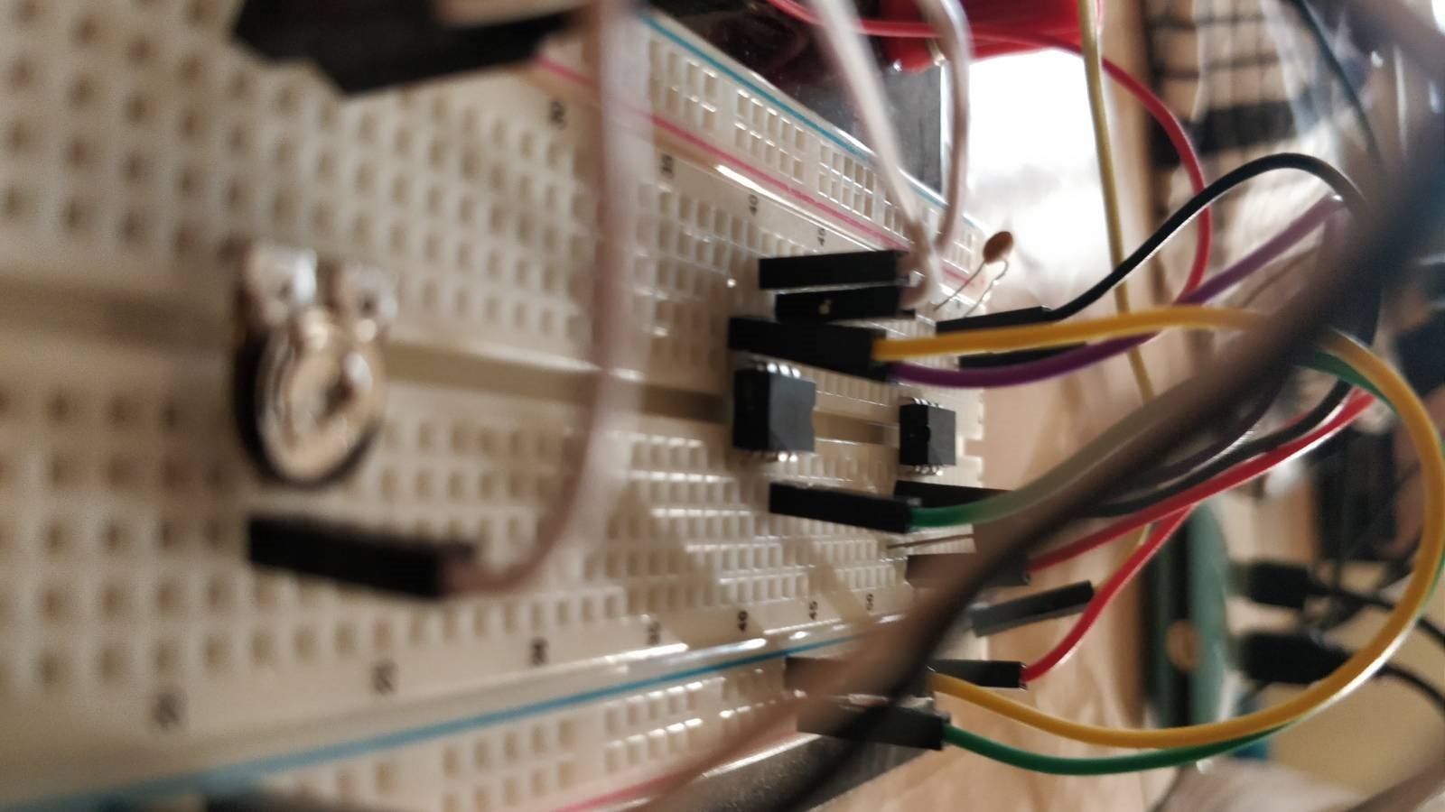
Then I thought to just use transducers of the ultrasonic sensors. I soldered one ultrasonic sensors transmitter pins and other ultrasonic sensor's receiver to jumper cables. The reason was that after the project I could de solder the wires and use it for something else.
Then I planned to use that as baseline to work on. But soon found out this great way how to do it on Hackaday. https://hackaday.com/2018/06/01/dead-simple-ultrasonic-data-communication/ . This tells us how important research is!
Basically what is happening is data is being transmitted by pulses of 2ms and 4ms for 0 and 1 respectively. On receiver side it is being measured as 0 or 1 and being reverses back to ASCII to character and printing it.
Part Required
- Arduino Uno // or any other
- Wemos D1 mini // or any other Wi-Fi enabled uC
- 2 ultrasonic sensors // or just transducers
- LM386 //to amplify sound waves
- LM 393 // as a comparator
- 10K potentiometer //for fine-tuning
- 100nF capacitor //to remove noise
- 10K resistor
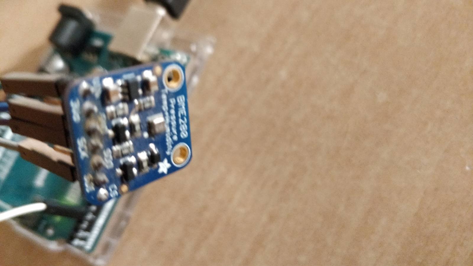
- BME 280 // temperature, humidity, air pressure sensor
| {gallery} Components |
|---|
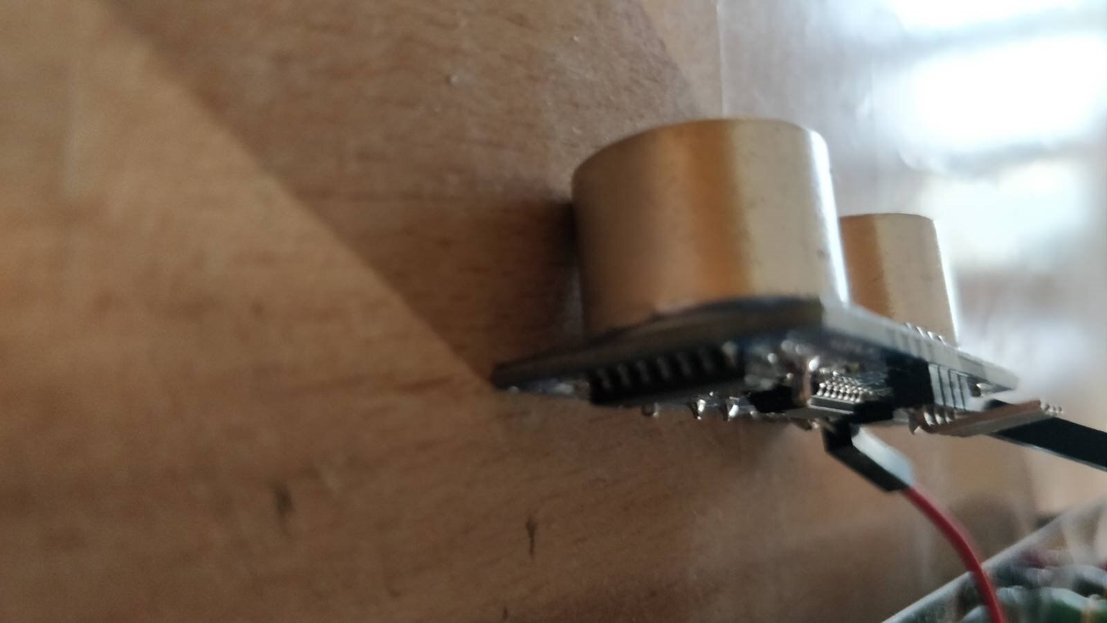
Ultrasonic Sensors , moreover ultrasonic transducers |
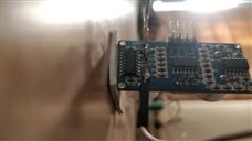
LM393+LM386 |
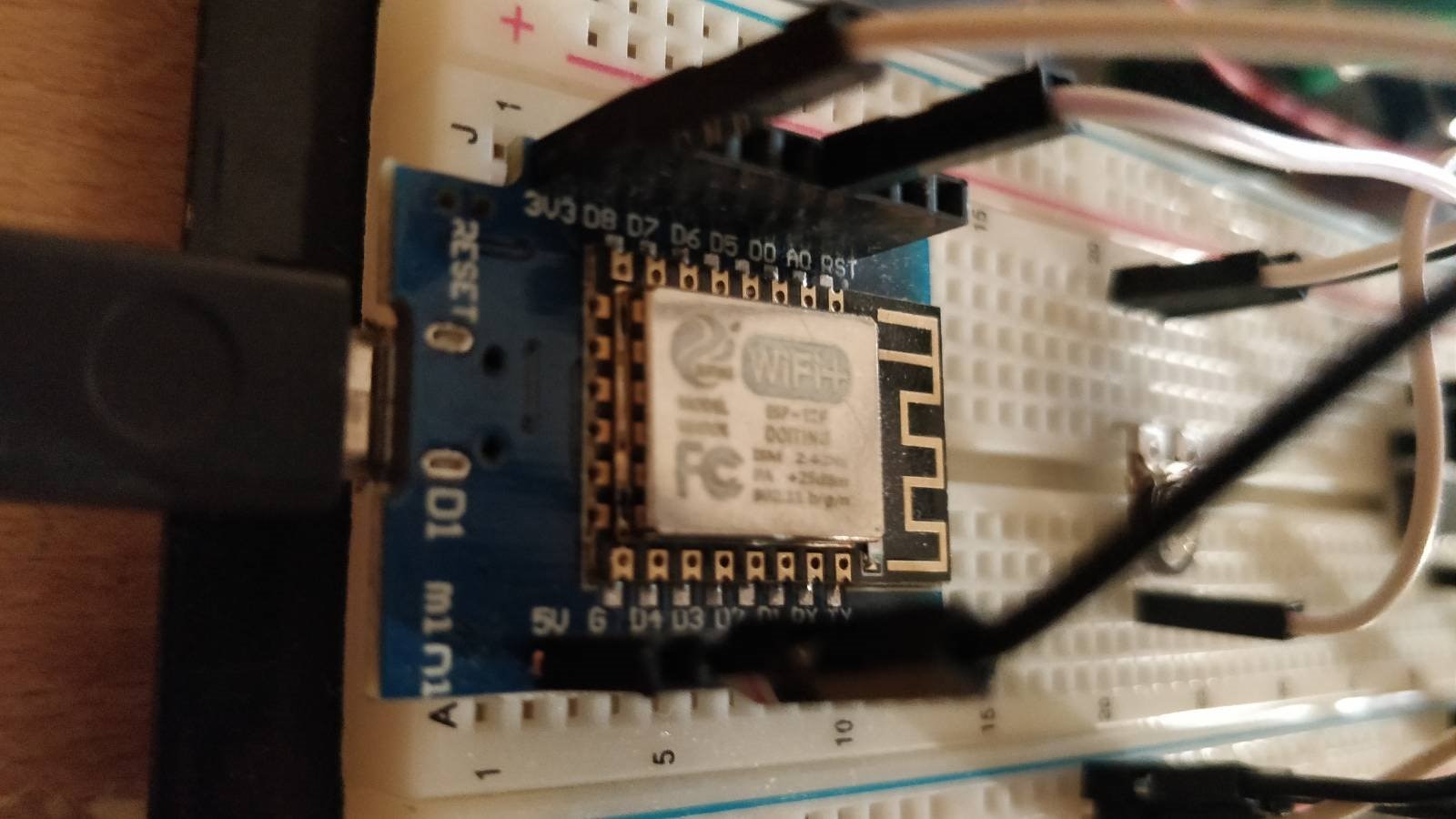
Wemos D1 MIni - uC with WiFi |
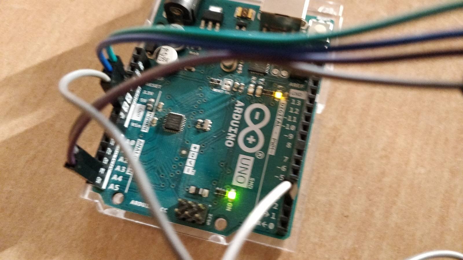
Arduino Uno |
BME280 Sensor |
Assembling
The schematic for the same is on the Hackaday post. I am just using wemos instead of an Arduino so that the data received can also be sent to the cloud. The only change is supply to comparator which will be 3.3v instead of 5v.
Schematic for receiver. Credit : the hackaday post
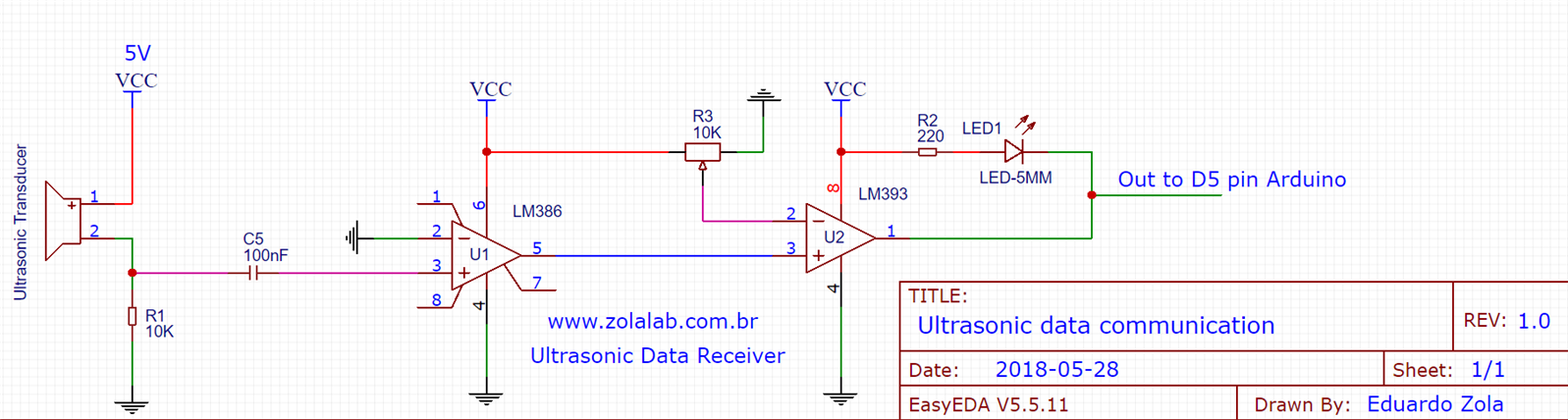
I did not connect the LED as found no practical use to it.
Schematic for Transmitter is pretty simple:
- Connect BME 280 sensor via I2C/SPI. I used I2C because it requires only 2 wires. Also connect VCC/Vin and GND pins of sensor to your development board.
- Connect the transducer's one pin to pin 3 and other to GND
The Transmitter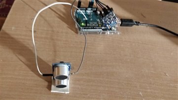
The Receiver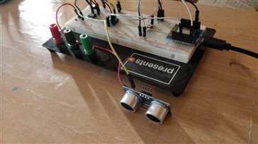
Working
Here is how it works:
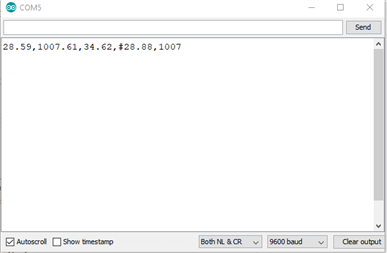
- Data us read from BME280 sensor on the transmitter and a string is made in this format : <temperature>,<pressure>,<humidity>,#
- The string is then broken into characters and each character into 8 bits ASCII Value.
- If it is 1 then the ultrasound pulse of 2ms and if 0 then of 4ms is formed. The "tone()" function of Arduino creates a very high vibrating frequency .
- On the receiver side data is received by measuring the time duration of which the pulse is their. Then it is converted to either 1 or 0 based on the pulse duration.
- Then the bits are converted to ASCII to characters and finally a string is formed.
- This string is then used to separate the temperature, air pressure and humidity values.
- The data is then pushed to Blynk cloud on pins V1, V2, V3 respectively.
Code
Sender Code https://gist.github.com/vimarsh244/dabe71cf9e18b30b88f72c52e9a638d6
Receiver Code https://gist.github.com/vimarsh244/d3d09b8dcfb82ff1f4a4e30a9d3687a1
Setting up Blynk Application - Cloud connectivity
Blynk is the easiest way to connect your Arduino/Raspberry Pi project to the cloud.
Blynk doesn't offer a webpage from where you can control/monitor your devices. All must happen through the smartphone app.
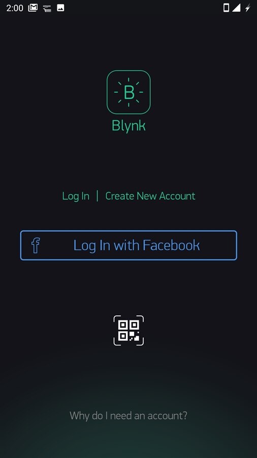
First step is to download the Blynk app from the Play Store/ App Store.
Then follow these steps to complete setting it up.
| {gallery} Setting up Blynk |
|---|
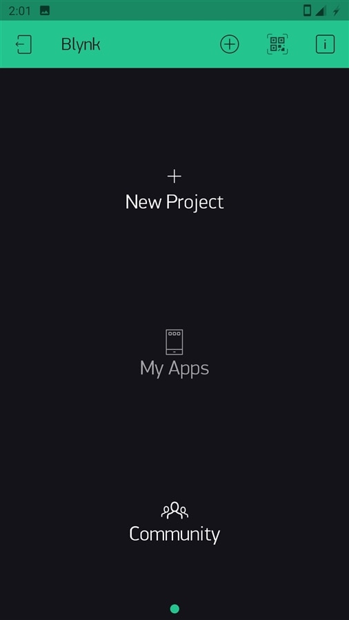
Once you open the app, you will be greeted with this screen. Click on create a new account. |
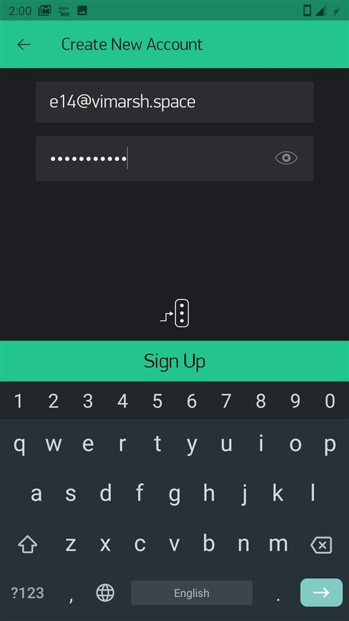
Enter your details and click on Sign Up |
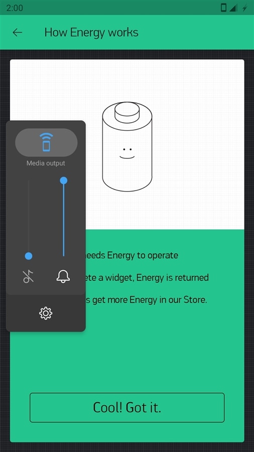
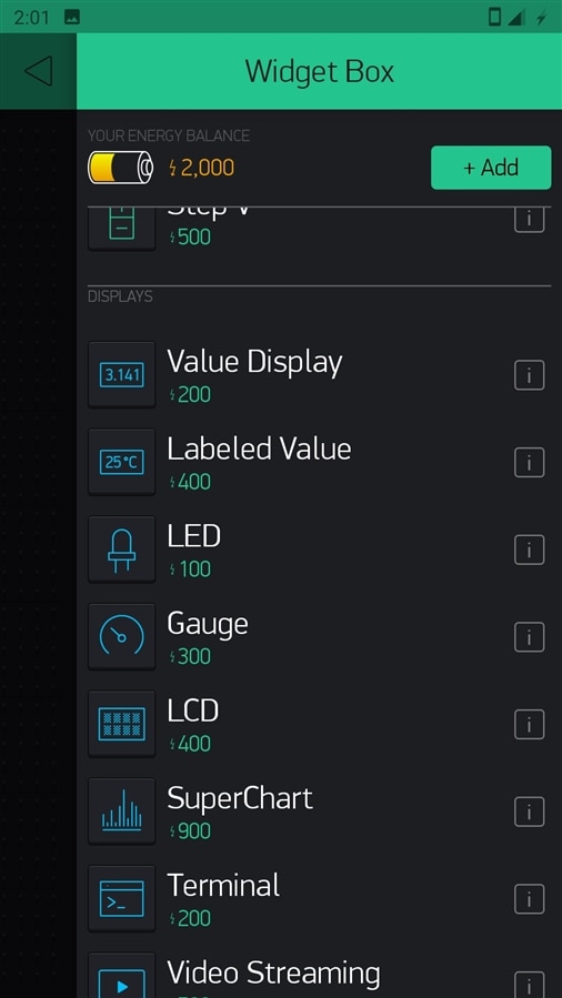
Here, you get to see that you will only be given 2000 energy. Energy is like a virtual coin in Blynk from which you can get several widgets. Widgets are various input/output graphical elements, |
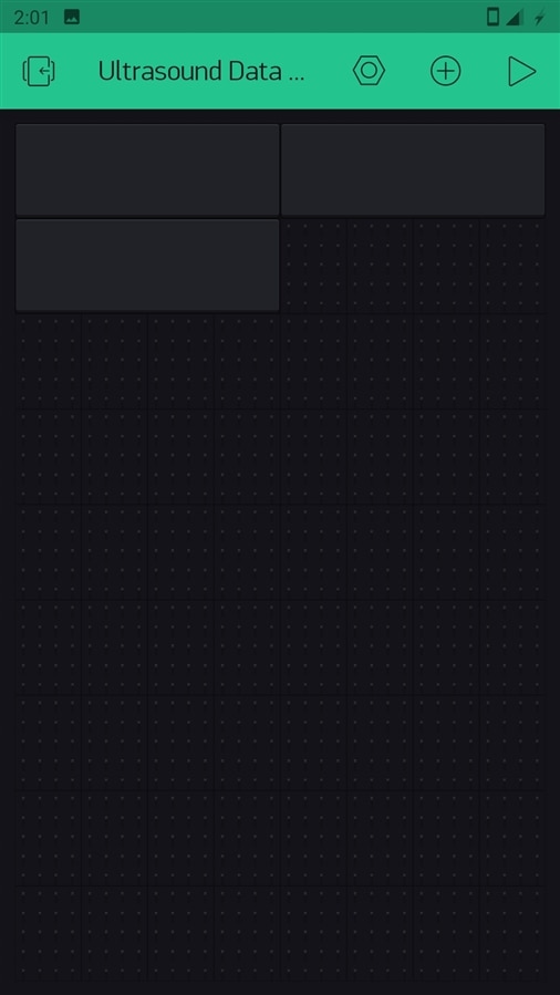
Click on new project |
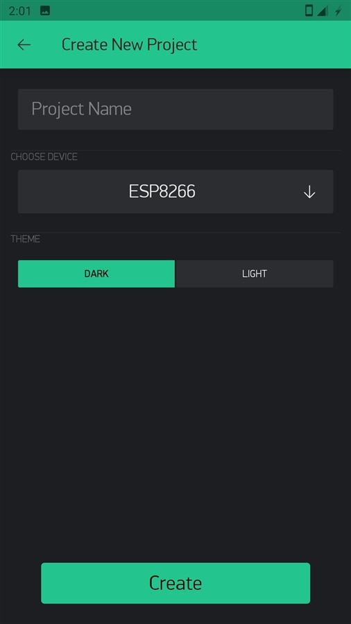
You will see this. Enter your project name and select correct device. For us that is ESP8266, the chip on the Wemos D1 mini |
|
|
|
|
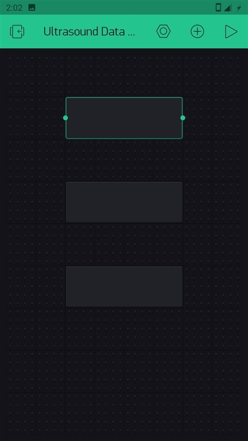
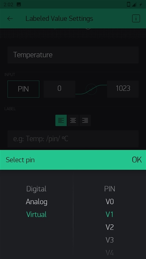
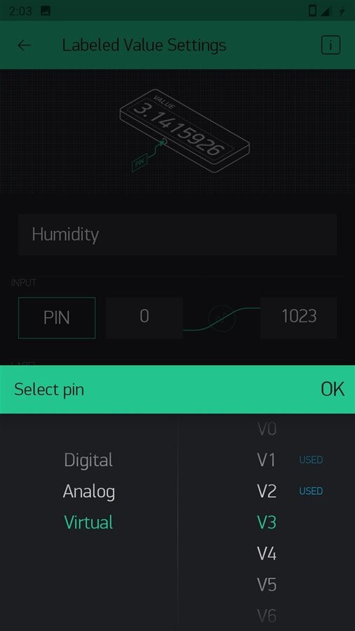
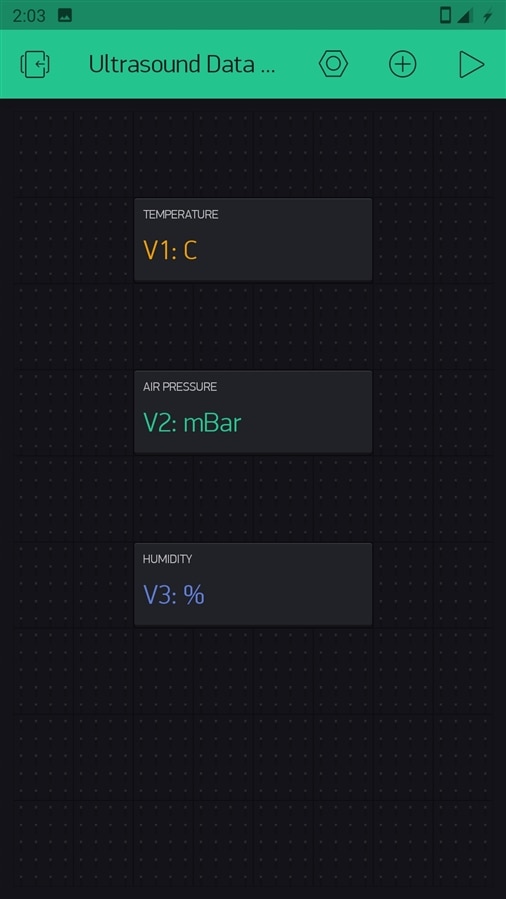
Click on one widget and name it temperature and select pin to Virtual and then V1 |
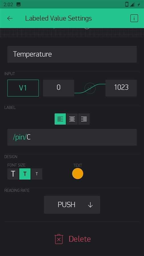
You can set text color,size,etc and the ending text after '/pin/' It will be different for every widget. |
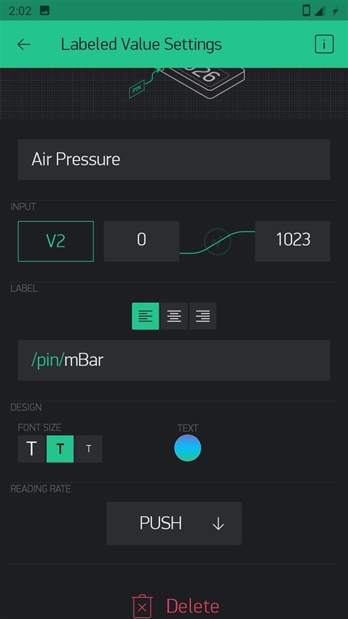
Do the same for Air Pressure with another widget |
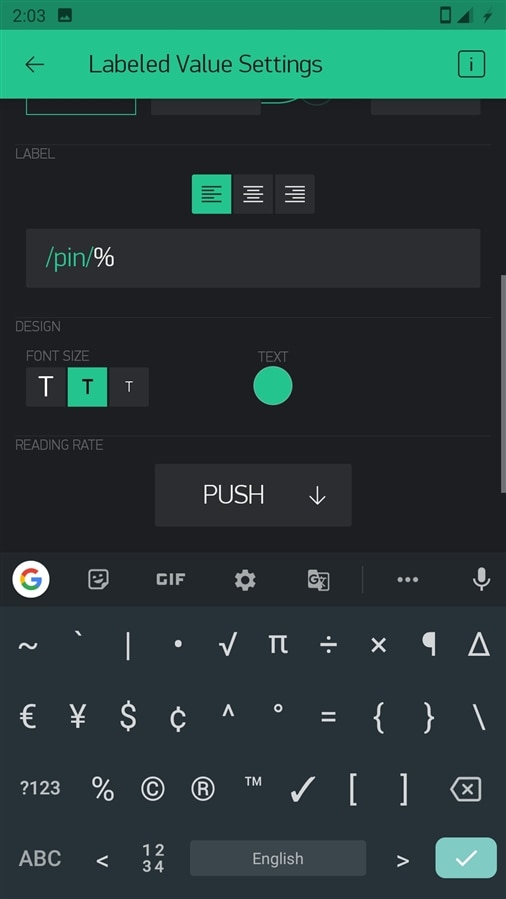
And the same for humidity |
Yo can type any symbol at the end. |
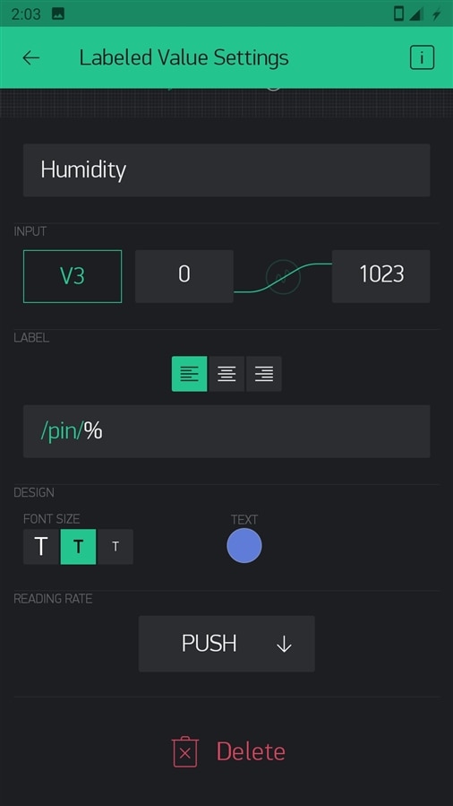
This is how humidity settings will look like |
And the configured screen. Then go to you Arduino IDE. and upload code. |
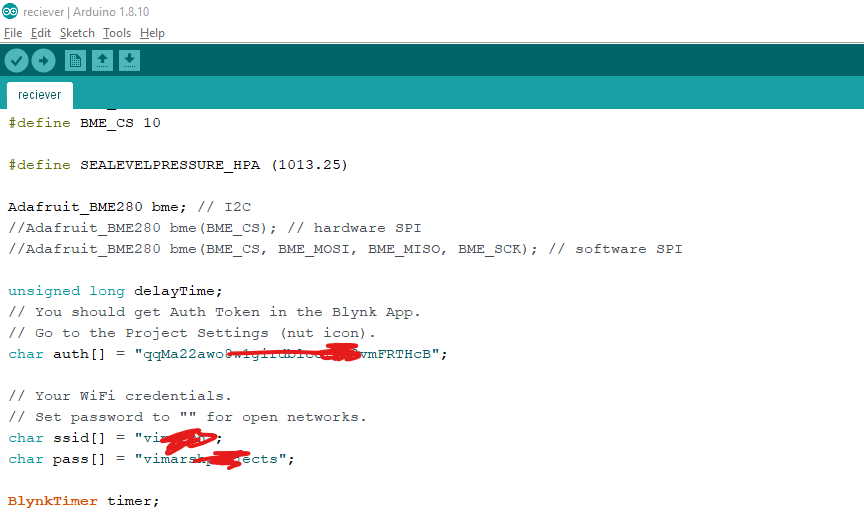
First don't forget to change the Auth token and WiFi Credentials in the code. |
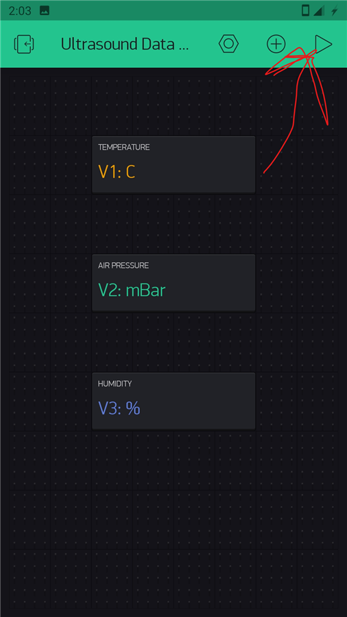
Then click on play button |
You will see your data from the sensor being transmitted via sound on your smart phone app. |
Also, because you are using a cloud service. You can download the app on any other phone and also see that data!
Results
You can listen to sensor sending data 3 times with one second delay in between: Listen here
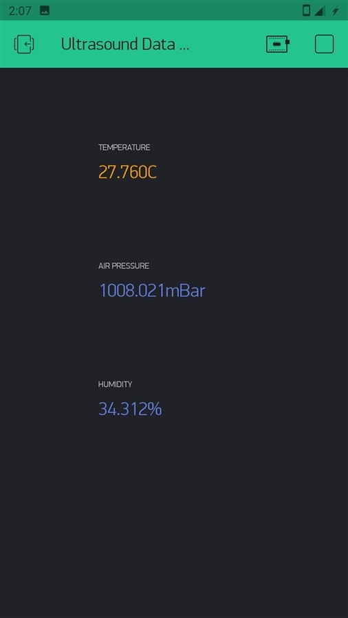
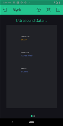
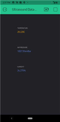
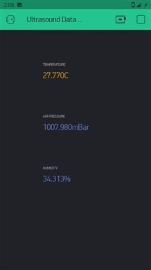
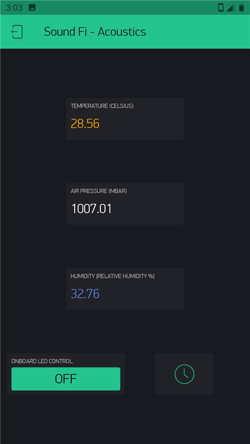
Here is the data on the Blynk app:

I found that the connection link was not stable for esp8266 to Blynk server perhaps because of code in-between which Blynk says no as because of delays the server session may time out.
Also, the distance between sensors and sensitivity may have to be tuned in a better way. Just if I had an oscilloscope!
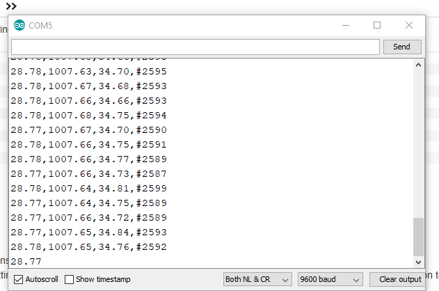
Data being received>
Speed of Transmission
I edited the code of receiver to find time it takes to received the full string. I turned out to be around 2600 ms.
long initial_time=micros();
...
//existing code
...
long final_time = micros();
long transmit_time= (final_time-initial_time)/1000;
Serial.println(transmit_time);
Here is output with that:
To calculate speed I measured the Bytes being sent and divided it by time it takes.
It is 21 bytes:
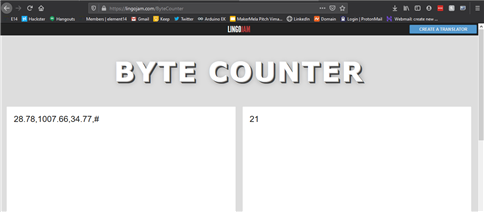
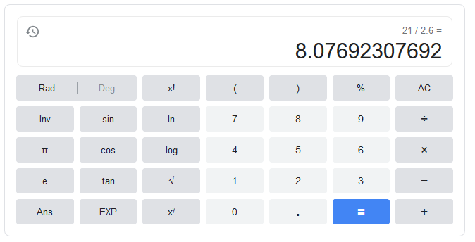
Dividing it by 2592 milli seconds
Speed = 8.077 bytes / second
The speed seems quite less and it is compared to WiFi and other RF. But that is still reasonable if we want to send some specific readings.
Read This
If you want to see the data on your smartphone which my device is transmitting. Then see the steps>
I will keep it on for some days probably and hopefully it will be transmitting. I live in Gujarat, India. So those are my indoor weather conditions. Also, I have added a button to control the onboard LED on the Wemos D1
Steps
| {gallery} My Gallery Title |
|---|
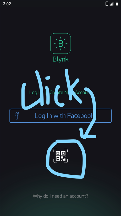
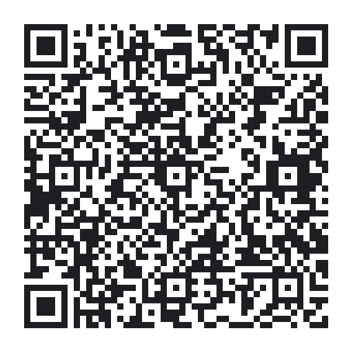
Click the QR Button |
Scan this QR Code |
Enjoy! |
Conclusion
This was a fun experiment for it. It was easy and a great insight on how to transmit data using sound.
Later I wish to add some sort of encryption and try for two way communication without interference.
Top Comments