SRD-1 - 3D Printed Drone (Arduino + Raspberry)
The newest update is the the June 11th Update - It flies, which can be found at the end of this blog!
1. Introduction & Idea
Hi! This will be my blog covering my build for the Attack of the Drones - Project14. My goal with this project is to design a quadcopter platform that I can equip with any amount of sensors I want, cameras, or anything else. Since this is a DIY drone on which I plan to play with flight algorithms, I am sure it will have its fair share of ground scraping, tree crashes, and wall slamming, so, I want this drone to be easily fixable, meaning, I want all of the mechanical components (except the propellers) be either 3D printable or can be made using commonly found materials and tools. I will cover the design for 2 versions of the drone here, one will have the body made out of two pieces of 3mm plywood, while the other one will be completely 3D printed. Most of the other parts will be interchangeable between the 2 versions. This first stage will have an off-the-shelf flight controller, which I will slowly try to replace using the 2 things that will be on board the drone, the Arduino and Raspberry.
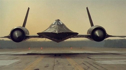
Now we can touch upon the name of my drone SRD-1. One of the coolest planes ever built to this day is the now-retired SR-71 Blackbird. It was a spy plane from the 1960s and it still stands as the fastest airplane ever built at a speed above 3.3 Mach. The SR in its name stands for Strategic Reconnaissance, and the plane is easily recognizable by the dark matte black paint which was also special in a sense of having small iron particles which would help with radar avoidance. Here are some pictures of this impressive plane.
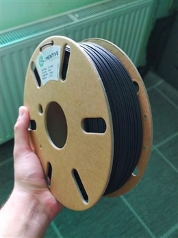
Now, how does my drone name and drone come into this? Well first, I think it's pretty clear that I'm a fan of this machine and what it could achieve, so, the name from the drone came from that obviously. The 1 at the end stands for the first concept/version of the drone, while the "D" in the name stands for "Drone". I've already explained that the "SR" in Blackbirds name stands for "Strategic Reconnaissance", but, since this won't be a spy drone, but rather a drone platform for me to play around with and conduct my research, the "SR" in the name will stand for "Science & Research", making the whole name of the drone: "Science & Research Drone 1". And, as a cherry on top, for this drone I've gotten a new role of PLA filament from Filamentive, their matte black filament, which will go perfectly with the name here.
2. Plan
I'm writing this after I've done everything (everything I could, since today, is the last day of this competition), so there have been major plan changes over which I'll go now. My initial plan was to use an off-the-shelf flight controller Naze32 (based on an STM32) and an off-the-shelf RadioLink transmitter and receiver. I of course assumed that I shouldn't worry about those parts, but of course, 3 days before the deadline, when I went to put everything together for the first time, the controller wasn't working, and the RC system was working a bit than not working. So, with 3 days to go, I decided to do the logical thing and to make my own Transmitter, Receiver, and Flight Controller.
Mechanical
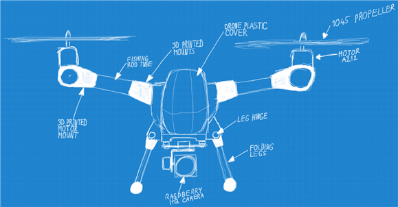
My wish was to do an H-frame drone, but that would require additional materials in the form of either carbon fiber tubes or fiberglass tubes. Since this was the first drone I ever made, I decided to go with only 3D printing to keep the costs down, and to be able to replace broken parts easier (foreshadowing....). To keep everything (or most of it) 3D printed, I decided to go with the X-frame instead as you can see from the drawings above. I will return to the H-frame for sure once I am satisfied with where this drone is. Here are some sketches I did for the H-frame drone before I started the build.
Another thing I changed was using plywood for the body of the drone and went completely with 3D printing. While 3D printing is a great tool, it's not the one tool end-all, so I wanted to use 3mm thick plywood for the body part of the drone. But when I cut it out, it was too wobbly, and since it is wood, you can't really expect to have a completely flat piece. The easiest solution would be to do a piece on the CNC, but since I don't have access to one, I decided to combine 2 parts into one and to have the base for the drone 3D printed, with some additional features as you will see in the blog.
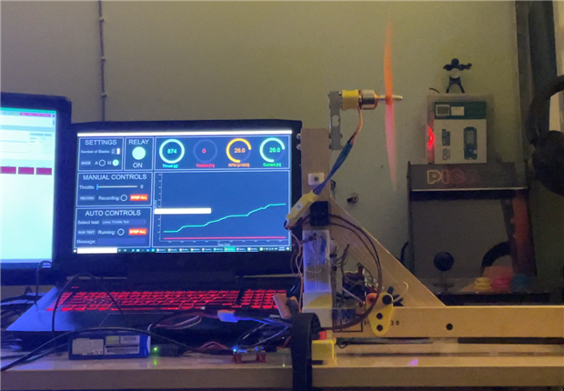
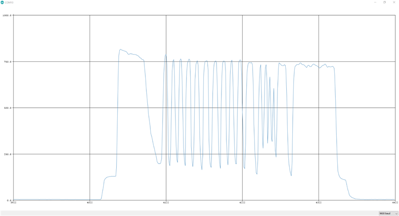
For the motors and propellers, I went for the A2212 BLDC motors and 1045 propellers. I paired the motors with 30A ESC as recommended by the buyer from who I've gotten the components. Now is a good time to see what can we expect to do with these motors and propellers. About 2 months ago, I made a test stand for testing the thrust of drone motors, you can find the whole project here: Drone Motor Thrust Tester. Long story short, it uses a load cell connected to the Arduino to measure the thrust that the motor is producing.
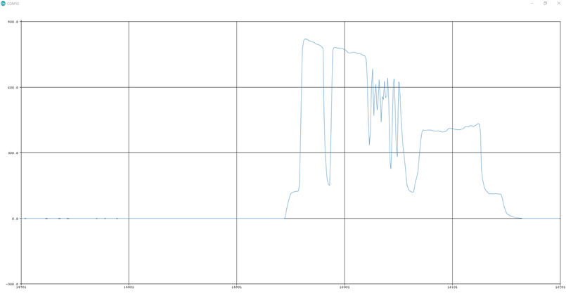
I've played around with the GUI code at one point and changed something, but can't figure out what I've done exactly, so there's a massive delay between the thrust and the measurememnt showing up on the screen. But nevertheless, the readings from the load cell are real, so the max load is the actual max thrust of a single motor
These motors are really powerful, and that LiPo makes a serious difference, in the end, we can see the maximum thrust of around 880g per motor.
Of course, the maximum weight of the drone is limited by the thrust of the motors. Looking at it online, it's recommended to have thrust 2 times bigger than the weight of the whole drone. So with each motor producing around 880g of thrust, that puts at a maximum thrust of around 3.5kg, which is a pretty big number. That means that our drone can easily be 1.7-1.8kg, though, even if we go a bit heavier, it won't be that big of a problem. Now it's time to take a look at the electronics I'm planning on using for this drone.
Electronics
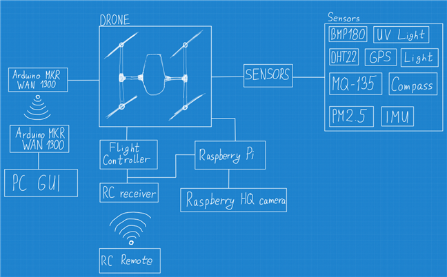
In the picture above, you can see a general idea for all of the electronics on the drone. As I've said previously, the flight controller, RC receiver and the RC remote were supposed to all be off-the-shelf products, but I had to go a different route. Since these were only the first tests that you will see in the blog, there won't be an Arduino MKR WAN1300 or Raspberry mounted, since I would have probably just broken them. Those are the things I will add a little bit later down the line when I get the drone flying nicely.
I've already covered the motors and controller, the A2212 BLDC motors, and generic 30A BLDC motors drivers to go with them.
3. Design
The design is split into 2 sections, the mechanical design, where I'll go over all of the 3D models for the drone as well as how all of them should be printed, and on the electronics design where I'll go over all of the small modules as well as the software for them. You can find all of the schematic, code, 3D models, and anything else related to this project also on my GitHub, if you wish to download any of the parts: https://github.com/MilosRasic98/SRD-1.
Mechanical Design
To design this, I used Fusion360 and this is by far the biggest and most complex assembly I've done to date. I've found the models for the motors, Raspberry, and propellers, all of the other models are my own designs. I've split the mechanical design into a few sections. There is the base assembly which includes the base, arms, and legs, the power assembly, which includes the battery and the power distribution module, and the electronics module, which includes the receiver and the flight controller. I've also designed a gimbal for the Raspberry HQ camera, I will cover that near the end of the blog if you're interested.
Base Assembly
As mentioned above, the base assembly consists of the base, which is made out of 2 base plates, drone arms, which hold the motors, legs for keeping the drone off the ground, and the feet for the drone. Here is the link for all of the models needed in the base assembly: https://github.com/MilosRasic98/SRD-1/tree/main/3D%20Models/Base%20Assembly
| {tabbedtable} Tab Label | Tab Content |
|---|---|
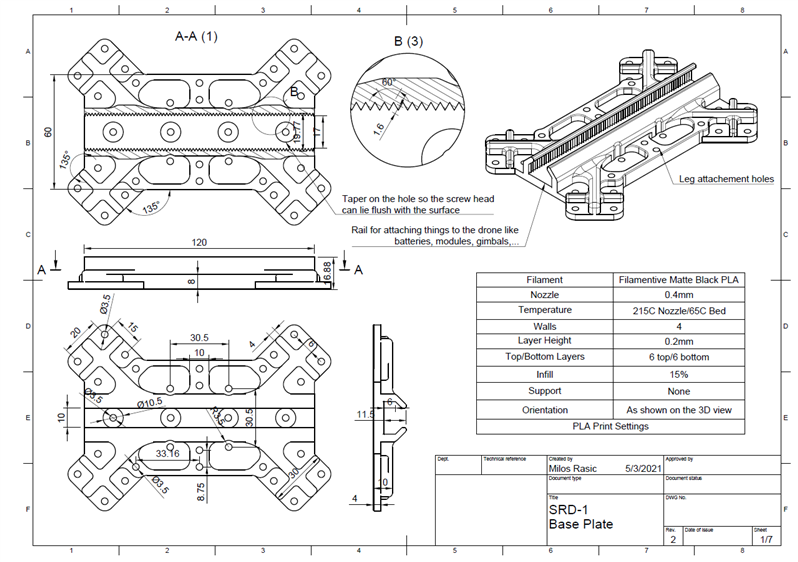
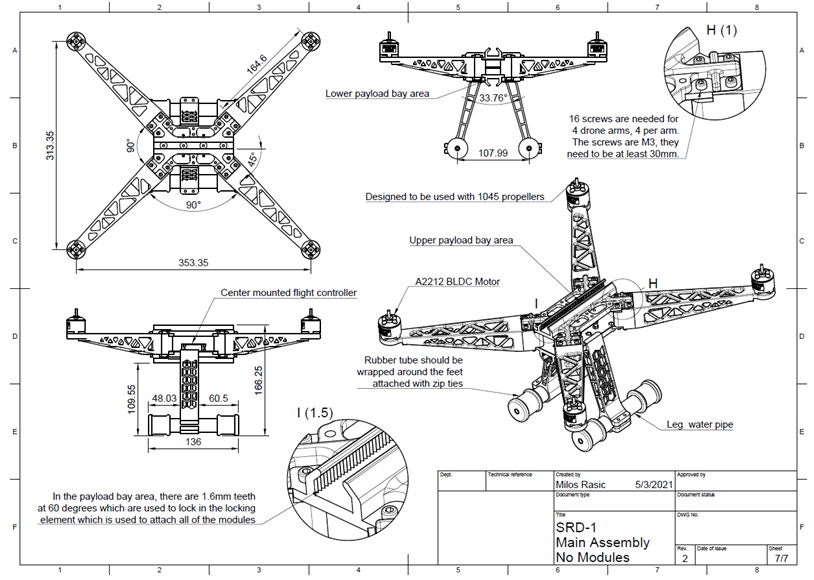
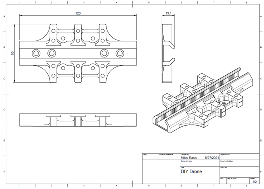
Base Plate | The base plate is pretty much the main component. The design consists of 4 arms in an X formation sandwiched between 2 base plates, everything held down with M3 screws and nuts. I originally wanted to use plywood instead of 3D printing, as it was supposed to be just a simple flat part, but the plywood I had was too warped. So I decided to combine the base plate with the "loading bay" to make one part. I'll explain the loading bay name in just a second. Since I want this drone to be adaptable for carrying either a camera, sensors, or something else, I designed a simple system for mounting parts to the drone. As you can see from the drawing, in the middle of the base plate there is a rail that has teeth on the inside. The idea is, to push in a locking element that has teeth on the outside which extend when you tighten a screw. How this locking element looks like, you can see in the next tab. Besides that, the base plate has 4 holes at 30.5mm apart that I planned on using for the STM32 controller, it has 4 holes in each corner for attaching the arms, and I left a few extra holes, with some of them having spaces for M3 nuts, so that we can more easily mount legs, or whatever else we desire. |
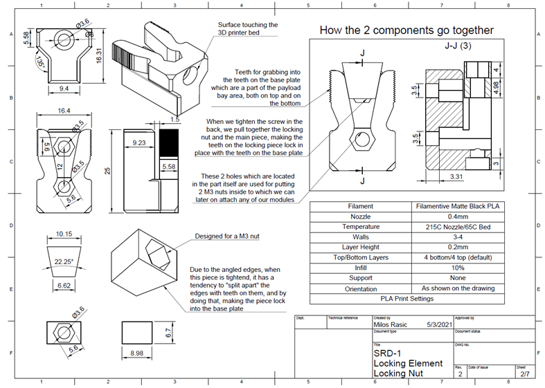
Locking Element | This element consists of 2 parts, the locking element itself and a locking element nut. The dimensions of this part are slightly smaller than those of the rail on the base plate, to accommodate for tolerances in 3D printing, but the part is essentially split down the middle. The locking element nut is a wedge-shaped piece that has a slot for an M3 nut. When we tighten the screw from one side, we pull in the wedge towards us, and in doing that, we make the teeth on the locking element lock in with the teeth on the rail. This proved to be a really tight and secure bond. |
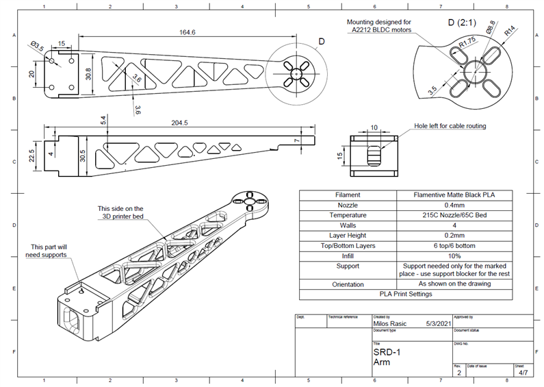
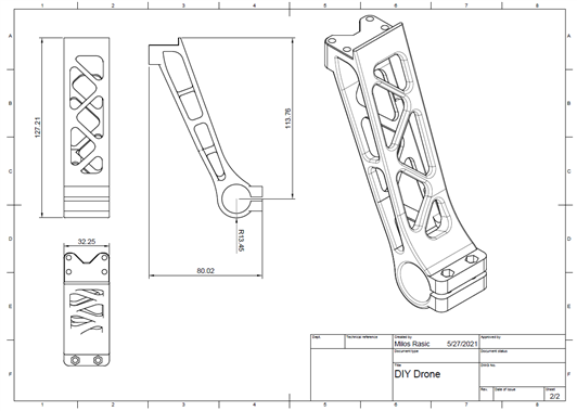
Arm | Now we have the arms of the drone. They were the trickiest to design by far when compared to all of the other pieces. They need to fit in with the base plate, they need to be really rigid, yet keep we need to keep the weight down and of course, since I'm using 10-inch propellers, I need to watch out for the spacing between the motors. The mounting holes for the motor are pretty universal, so they can be used with other similar-sized motors as well probably. Foreshadowing again, but, the print setting needs to be revised a bit, and, maybe even the design, needs more plastic near the top of the arm where the motor mounts. Except for fort the beginning of the arm where it attaches to the base plate, this can be printed completely support-free, with maximum overhangs of around 25mm. |
Leg | The legs mount on the underside of the lower base plate. I tried saving some weight on them by making everything super thin, but they turned out a bit weaker than I wanted, and also a bit narrower than I would have liked, which caused me some issues when I wanted to mount stuff underneath. So this is one part that will get a complete redesign for sure. |
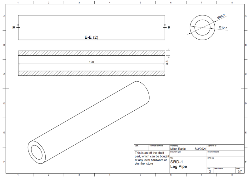
Leg Pipe | Rather than just printing out a tube, I found some old PVC water pipe laying around, and it looked like the perfect candidate for using it as a part of my leg. It's not completely straight and incredibly strong, so it won't do the job for the drone arms, but it will do great here. The legs grab onto the pipe with 2 M3 screws and nuts. I've left the hole slightly bigger with a gap in the lower part of the leg, so it clamps down really good and firmly when we tighten up the screws. |
Foot | The last part here is the foot for the drone. It works in exactly the same way as I've described the locking element. Just this time, 2 things spread out to make a friction fit with the inner walls of the water pipe. |
In the end, we have an assembly that looks like this:
Power Assembly
This assembly consists of 2 modules, one is the battery module that takes care of mounting the battery to the drone and the other one is the power distribution module, which purpose is to get all of that power to the ESC-s and motors as well as to our other electronics. Unfortunately, I had problems with soldering anything to the power distribution module without setting the wires on fire, so this is something that I'll have to revisit. For testing purposes, I did the power distribution using just some 2.5mm^2 silicon wires.
Battery Module
The idea is to have the battery hanging down below the drone. I chose that option because the middle isn't big enough and I wanted to keep the top free for other electronics, especially when I get to use a GPS module. To make the moment of inertia smaller, I wanted to mount the battery as close to the middle as possible, or, in other words, as close to the lower base plate as possible. Models: https://github.com/MilosRasic98/SRD-1/tree/main/3D%20Models/Power%20Assembly
| {tabbedtable} Tab Label | Tab Content |
|---|---|
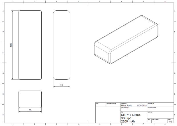
3S 2200mAh Lipo | For powering the drone I went with a Lipo battery which is a standard for quadcopters due to the insane amount of current they can provide. I went with a Turnigy 3S 2200mAh Lipo with a 40-50C discharge. This battery should provide more than enough power, and the capacity isn't bad. I want to see how long of a flight I can achieve on a single charge since I have a lot of headroom when it comes to weight, so I could maybe even mount another battery in parallel to this one. Here are the rough dimensions as a guideline that I used for designing the rest of the module. |
Battery Tray | To mount the battery, I designed a battery tray which is supposed to be mounted on the rail on the lower base plate. The battery tray is designed to use a velcro strap to hold the battery in place while the drone is flying. |
Long Locking Element | This is just an extended version of the locking element, all of the other dimensions are the same. The only difference is that the holes where something mounts to the locking element are offset by 30mm compared to the normal version. |
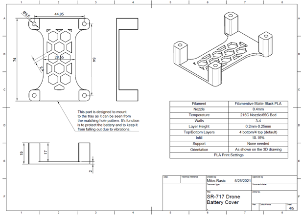
Battery Cover | The last piece is the battery cover. This cover screw into the 4 holes on the battery tray. The tray has holes left for embedded M3 nuts. While this cover is not necessary, it can provide additional protection for the battery and if we desire, we can design it so that we can mount other things to it. |
The full assembly, in the end, looks like this.
Power Distribution Module
As I've mentioned above, I've designed this module but didn't manage to integrate it. I tried soldering the wires using a gas soldering iron since the normal one isn't powerful enough. But I just ended up setting a few wires on fire and nothing else. The idea behind this module was to have 2 copper strips with soldered wires attached to an XT60 connector for the battery. Here is how it's supposed to look like.
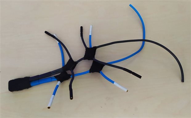
Because I wasn’t able to do that, I made a simple wiring loom to distribute the power to all of the components using some 2.5mm^2 wires and bullet connectors. It’s not the nicest looking thing in the world, but it does the job great.
Electronics Assembly
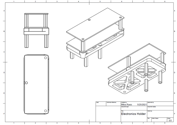
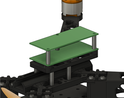
This here is the last part I've designed for the whole drone. I needed a way to mount the receiver and the flight controller that were both on 2 pieces of perf board, so I came up with this easy way of mounting using some M3 spacers. The flight controller should be on the bottom, to keep the IMU as close to the middle of the drone as possible, with the receiver on the top. To mount all of this to the drone, I decided to go with the 4 holes I already had on the upper base plate for the STM32 flight controller.
As for what's exactly on these boards, you will see in the next section. The only thing that had to be printed out for this was the holder piece that you can see underneath the boards. It just had to adapt the holes from the drone to some holes that were already on the boards as well as another one that I made. Models: https://github.com/MilosRasic98/SRD-1/tree/main/3D%20Models/Electronics%20Assembly
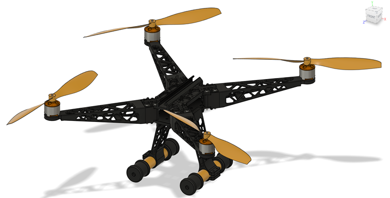
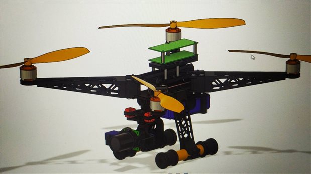
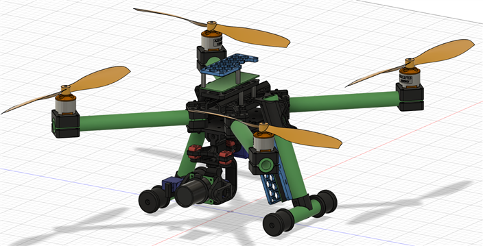
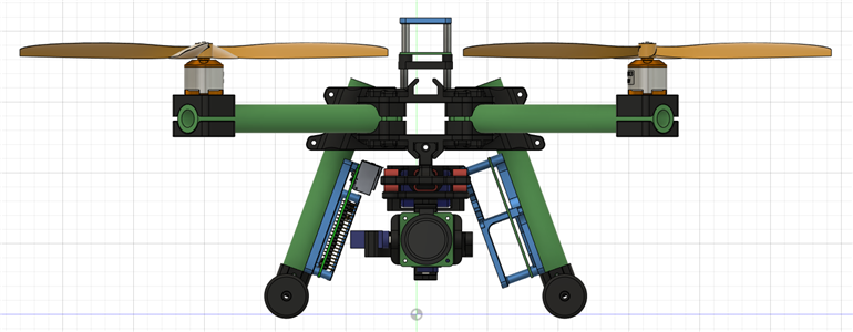
3D modelling took a nice amount of time, in the end, through different versions of sub-assemblies, my file had somewhere around 200 components in total. Here is how the whole drone looks like in CAD.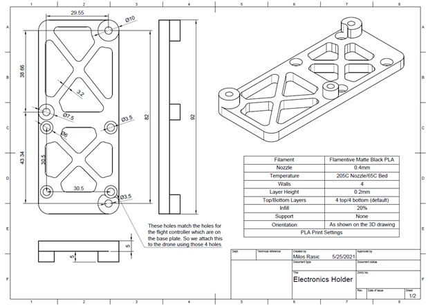
Electronics Design
This part was initially supposed to be really simple, connecting the ESC-s to the flight controller, the motors to the ESC-s, everything to the battery, and adding the Raspberry with the camera. But of course, as I've said before, everything turned upside down 3 days ago, so I had a lot of work to do and not a lot of time. The best thing that I've done in that short period of time was taking half a day break away from home, where I've gone online and researched my option. That's when I've found MultiWii as well as an amazing tutorial series by Electronoobs. I can't stress enough, how much his tutorial helped me to get this done in time. If you haven't heard of him before, he's an electronics Youtuber from Spain, who does all sorts of projects with really nice explanations (https://www.youtube.com/channel/UCjiVhIvGmRZixSzupD0sS9Q ). I found some other tutorials, but his Arduino drone tutorial is what made me able to finish in time.
It was too late to go out and buy a new RC transmitter and receiver and flight controller (not to talk to about expensive). So I decided to follow what Electronoob did. The idea is to use an NRF24 module for the Arduino to make an RC transmitter/receiver pair as well as a flight controller. Going through my drawers, I managed to find 3 Arduino Nanos, since I use them for everything. In other words, one Arduino will be used for the RC transmitter, one for the RC receiver, and one for the flight controller. I tried using the Arduino MKR WAN 1300 boards for this since I want to get Lora working as well at one point, but the NRF24 libraries don't work on those boards, unfortunately. I will now go over each one of the modules.
Before I start going into the NRF24 modules, I just want to give one really really important tip. First of all, those modules work on 3.3V, so watch out to not fry them with 5V, also, the module with the antenna can consume over 100mA, which is over the current capacity of the Arduino Nano 3V3 regulator, so you will need another regulated 3V3 source. And the last thing, do not use jumper cables. Solder all of the wires directly to the module and solder an electrolytic capacitor to the pins of the modules. I had so many problems with those jumper wires having a bad contact somewhere, I was sure the modules were bad, and just soldered on the wires as the last desperate move, and it finally worked for the first time.
RC transmitter
Rather than spending hours and hours on designing a special enclosure for my transmitter (at least for now), I will stick with the design of the controller I already have. The transmitter in question is a RadioLink T6EHP-S. The roll stick on it was trashed from the beginning, with it giving sometimes good reading and sometimes completely wrong values. I opened it up to see that the potentiometer sometimes gave good values, sometimes bad. I thought it had something to do with solder joints since the wires and solder joints left a lot to be desired if I'm honest.
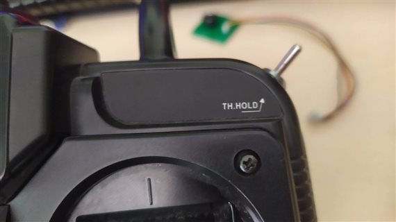
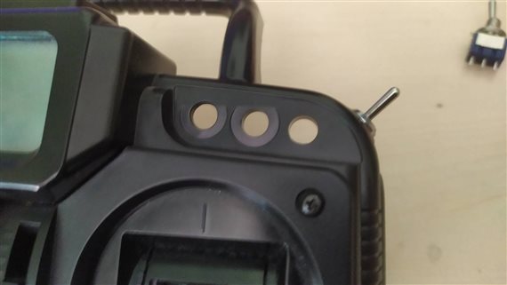
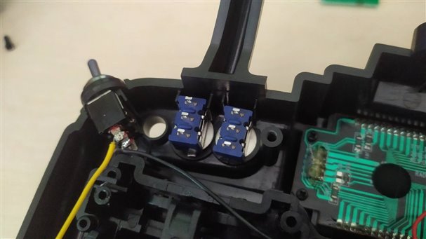
I had this remote for quite a few years, and I hadn't really used it a lot, and it was broken. So, I thought I would give it a makeover with an Arduino Nano and additional switches and joysticks. One thing I found out when I opened up the transmitter is that the stickers cover a lot of holes for higher-end modules which have more switches and stuff like that.
And as luck would have it, I had some of the toggle switches, that match those in the transmitter exactly, which meant they also matched the empty holes that you can see on the second picture.
The only thing we need now are wires and an Arduino Nano. A lot of wires as you can see.
Another thing that came out looking really good is that the antenna from the NRF24 module fits great with a little modification into the place where the old antenna was. To keep the number of components down, I've tied all of the toggle switches to pull to ground and used internal pullups on the Arduino pins.
And here you can see everything wired up and soldered on. I've put small tags on all of the wires before I started soldering which made my life so much easier. I've mounted the Arduino up to one of the sides of the transmitter and cut out a hole for the USB connector, so it can be powered via USB and can also be programmed. The connections for this are really simple. The NRF24 is connected via SPI and to pins 7 and 8, the switches are connected to all of the other digital pins, and the joysticks are connected to all of the analog pins except A4 and A5. I left A4 and A5 free because they are used for I2C, so I can easily add a small OLED display or something similar later down the line. Here is how it looks from the front.
The original transmitter had only 6 channels, which is enough for controlling the drone, but now it has 13 channels and I can upgrade it to have 32 channels (unless I break the data into more messages). I've added 4 switches, and an Arduino Joystick module with a click. The main idea for the joystick is to have control over the camera gimbal.
RC receiver
The RC receiver, as mentioned before, also uses an Arduino Nano. Besides the NRF24 that is used for communicating with the transmitter and a connector for PPM communication with the flight controller, I've also added 2 connectors for servo motors for the gimbals as well as a connector for sending a signal to the Raspberry to start recording.
Raspberry work on a 3.3V logic level, getting 5V on one of the pins can cause damage to the Raspberry. To avoid this, you can either use an off-the-shelf shifter circuit or make your small shifter in a variety of different ways, from using a comparator, voltage divider, optocoupler and so on.
I've decided to go with a small 4N27 optocoupler to drop down the level from 5V to 3.3V. Here is the circuit that's needed to do just that.
To finish up the receiver, I've just soldered everything to a piece of perf board.
Flight Controller
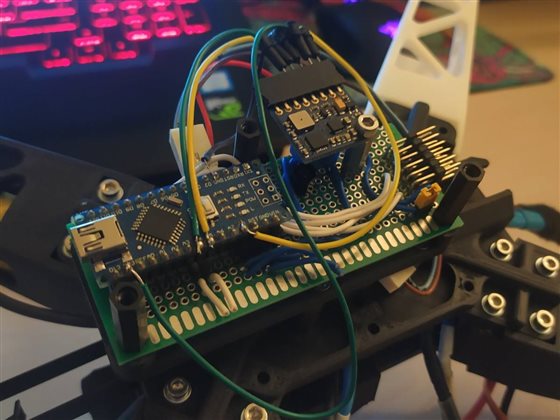
The last board that I had to make was the flight controller, and this was the simplest of the bunch. The flight controller, in this case, consists of the Arduino, an IMU, a connector for power, a connector for PPM, and connectors for the ESC-s. I'm using the Arduino Nano as mentioned before, but, now we come to the IMU. And this was the last problem I had to deal with. I had 2 IMU-s in my components, a GY-521, and a GY-88. For no reason that for having male headers soldered on, I went with the GY-521 IMU, which turned out to be a big issue. For some reason, I couldn't upload the code after soldering the wires to the IMU, without pulling the Arduino out of its socket and MultiWii GUI would just crash on me. I don't know if it had something to do with my soldering where I've connected something by accident (though I've checked many times) or was it just a bad IMU. The first flight tests failed because of this as well, the drone would work great for about a minute, and then the motors would just turn off, the same thing that was happening with the GUI. But, after changing to the GY-88 in the last second, I managed to get it off the ground. The GY-521 was soldered in nicely and positioned properly, since the GY-88 was a last-minute move, it's soldered in really fast and not in the nicest way.
I've cut out the exact same piece of perf board for the flight controller as I did for the receiver so I can stack them up one on top of the other. The small yellow jumper that can be seen in the bottom right corner is used for choosing the power supply for this electronics section. The ESC-s have their own regulated 5V which you can use to power the Arduinos, which I did. If you remove the jumper, you have to provide power in a different way, I left this option so I can use an external buck converter, since I needed a lot of power for the Raspberry and already planned on having one on the drone.
4. Software
The software section is split into 2 parts, RC transmitter & receiver, and flight controller. I encountered some problems, that I think I should mention, as it might help others who run into similar problems if they try doing their own version of this.
RC Transmitter & Receiver
The receiver will communicate with the flight controller using PPM which stands for Pulse Position Modulation. The heavy weightlifting here was done in the Electronoobs tutorial. I've adapted that code to work for me, with my additional outputs and tested out some other functionalities, like moving servos. The goal for us is to have a test code in the end as well that will write out all of the reading from our remote.
Transmitter
// TRANSMITTER CODE


/*
 *  This code will be used for sending data using the NRF24 to the Arduino on our drone
 *
 *  Connections for this transmitter are:
 *  NRF24 - standard SPI connection and the other 2 pins to pins 7 & 8
 *  All of the switches are connected to digital pins, they are wires up so they pull the input to ground,
 *  this is so we can use an internall pullup on Arduino pins
 *  On the analog pins we have all of the joysticks from our transmitter
 *  A4 and A5 are left unconnected so we can have I2C devices further on if we desire
 *
 */


/*
 *  This code is a modified version of the code from Electronoobs.com
 *  Check out his tutorial on the Arduino Drone
 *
 */

#include <SPI.h>
#include <nRF24L01.h>
#include <RF24.h>


#define Pin_AUX1 2
#define Pin_AUX2 3
#define Pin_AUX3 4
#define Pin_AUX4 5
#define Pin_AUX5 6
#define Pin_AUX6 9
#define Pin_AUX7 10


/*Create a unique pipe out. The receiver has to
  wear the same unique code*/

const uint64_t pipeOut = 0xE8E8F0F0E1LL;


RF24 radio(7, 8); // select  CSN  pin


// The sizeof this struct should not exceed 32 bytes
// This gives us up to 32 8 bits channals
struct MyData {
  byte throttle;
  byte yaw;
  byte pitch;
  byte roll;
  byte AUX1;
  byte AUX2;
  byte AUX3;
  byte AUX4;
  byte AUX5;
  byte AUX6;
  byte AUX7;
  byte gimbalY;
  byte gimbalZ;
};


MyData data;


void resetData()
{
  data.throttle = 0;
  data.yaw = 127;
  data.pitch = 127;
  data.roll = 127;
  data.AUX1 = 0;
  data.AUX2 = 0;
  data.AUX3 = 0;
  data.AUX4 = 0;
  data.AUX5 = 0;
  data.AUX6 = 0;
  data.AUX7 = 0;
  data.gimbalY = 0;
  data.gimbalZ = 0;
}


void setup()
{
  //Start everything up
  pinMode(Pin_AUX1, INPUT_PULLUP);
  pinMode(Pin_AUX2, INPUT_PULLUP);
  pinMode(Pin_AUX3, INPUT_PULLUP);
  pinMode(Pin_AUX4, INPUT_PULLUP);
  pinMode(Pin_AUX5, INPUT_PULLUP);
  pinMode(Pin_AUX6, INPUT_PULLUP);
  pinMode(Pin_AUX7, INPUT_PULLUP);
  radio.begin();
  radio.setAutoAck(false);
  radio.setDataRate(RF24_250KBPS);
  radio.openWritingPipe(pipeOut);
  resetData();
}


int mapJoystickValues(int val, int lower, int middle, int upper, bool reverse)
{
  val = constrain(val, lower, upper);
  if ( val < middle )
    val = map(val, lower, middle, 0, 128);
  else
    val = map(val, middle, upper, 128, 255);
  return ( reverse ? 255 - val : val );
}


void loop()
{
  data.throttle = mapJoystickValues( analogRead(A0), 60, 490, 925, true );
  data.yaw      = mapJoystickValues( analogRead(A1),  0, 520, 956, false );
  data.pitch    = mapJoystickValues( analogRead(A2), 44, 502, 934, true );
  data.roll     = mapJoystickValues( analogRead(A3), 31, 320, 608, false );
  data.gimbalY  = map(analogRead(A6), 0, 1023, 0, 255);
  data.gimbalZ  = map(analogRead(A7), 0, 1023, 0, 255);
  data.AUX1     = digitalRead(Pin_AUX1);
  data.AUX2     = digitalRead(Pin_AUX2);
  data.AUX3     = digitalRead(Pin_AUX3);
  data.AUX4     = digitalRead(Pin_AUX4);
  data.AUX5     = digitalRead(Pin_AUX5);
  data.AUX6     = digitalRead(Pin_AUX6);
  data.AUX7     = digitalRead(Pin_AUX7);
  radio.write(&data, sizeof(MyData));
}
Receiver
// RECEIVER


/*
 * This codes reads all of the channels from out transmitter and packs them into our PPM signal
 * For testing purposes, we can add Serial prints for all of the values to check if everything is working correctly
 * The roll on my transmitter is broken (bad potentiometer), so I've programmed the receiever to ignore that channel
 * unless a specific AUX is activated
 */


/*
 *  This code is a modified version of the code from Electronoobs.com
 *  Check out his tutorial on the Arduino Drone
 */


#include <SPI.h>
#include <nRF24L01.h>
#include <RF24.h>


////////////////////// PPM CONFIGURATION//////////////////////////
#define channel_number 6  //set the number of channels
#define sigPin 2  //set PPM signal output pin on the arduino
#define PPM_FrLen 27000  //set the PPM frame length in microseconds (1ms = 1000µs)
#define PPM_PulseLen 400  //set the pulse length
//////////////////////////////////////////////////////////////////


int ppm[channel_number];


const uint64_t pipeIn =  0xE8E8F0F0E1LL;


RF24 radio(7, 8);


// The sizeof this struct should not exceed 32 bytes
struct MyData {
  byte throttle;
  byte yaw;
  byte pitch;
  byte roll;
  byte AUX1;
  byte AUX2;
  byte AUX3;
  byte AUX4;
  byte AUX5;
  byte AUX6;
  byte AUX7;
  byte gimbalY;
  byte gimbalZ;
};


MyData data;


void resetData()
{
  // 'safe' values to use when no radio input is detected
  data.throttle = 0;
  data.yaw = 127;
  data.pitch = 127;
  data.roll = 127;
  data.AUX1 = 0;
  data.AUX2= 0;
  data.AUX3 = 0;
  data.AUX4 = 0;
  data.AUX5 = 0;
  data.AUX6 = 0;
  data.AUX7 = 0;
  data.gimbalY = 1500;
  data.gimbalZ = 1500;

  setPPMValuesFromData();
}


void setPPMValuesFromData()
{
  ppm[0] = map(data.throttle, 0, 255, 1000, 2000);
  ppm[1] = map(data.yaw,      0, 255, 1000, 2000);
  ppm[2] = map(data.pitch,    0, 255, 1000, 2000);
  if(data.AUX3 == 1){
      ppm[3] = 1500;
    }
    else{
        ppm[3] = map(data.roll,     0, 255, 1000, 2000);
      }
  ppm[4] = map(data.AUX1,     0, 1, 1000, 2000);
  ppm[5] = map(data.AUX2,     0, 1, 1000, 2000);
  }


/**************************************************/


void setupPPM() {
  pinMode(sigPin, OUTPUT);
  digitalWrite(sigPin, 0);  //set the PPM signal pin to the default state (off)


  cli();
  TCCR1A = 0; // set entire TCCR1 register to 0
  TCCR1B = 0;


  OCR1A = 100;  // compare match register (not very important, sets the timeout for the first interrupt)
  TCCR1B |= (1 << WGM12);  // turn on CTC mode
  TCCR1B |= (1 << CS11);  // 8 prescaler: 0,5 microseconds at 16mhz
  TIMSK1 |= (1 << OCIE1A); // enable timer compare interrupt
  sei();
}


void setup()
{
  resetData();
  setupPPM();

  // Set up radio module
  radio.begin();
  radio.setDataRate(RF24_250KBPS); // Both endpoints must have this set the same
  radio.setAutoAck(false);


  radio.openReadingPipe(1,pipeIn);
  radio.startListening();
}


/**************************************************/


unsigned long lastRecvTime = 0;


void recvData()
{
  while ( radio.available() ) {
    radio.read(&data, sizeof(MyData));
    lastRecvTime = millis();
  }
}


/**************************************************/


void loop()
{
  recvData();


  unsigned long now = millis();
  if ( now - lastRecvTime > 1000 ) {
    // signal lost?
    resetData();
  }

  setPPMValuesFromData();
}


/**************************************************/


//#error Delete this line befor you cahnge the value (clockMultiplier) below
#define clockMultiplier 2 // set this to 2 if you are using a 16MHz arduino, leave as 1 for an 8MHz arduino


ISR(TIMER1_COMPA_vect){
  static boolean state = true;


  TCNT1 = 0;


  if ( state ) {
    //end pulse
    PORTD = PORTD & ~B00000100; // turn pin 2 off. Could also use: digitalWrite(sigPin,0)
    OCR1A = PPM_PulseLen * clockMultiplier;
    state = false;
  }
  else {
    //start pulse
    static byte cur_chan_numb;
    static unsigned int calc_rest;


    PORTD = PORTD | B00000100; // turn pin 2 on. Could also use: digitalWrite(sigPin,1)
    state = true;


    if(cur_chan_numb >= channel_number) {
      cur_chan_numb = 0;
      calc_rest += PPM_PulseLen;
      OCR1A = (PPM_FrLen - calc_rest) * clockMultiplier;
      calc_rest = 0;
    }
    else {
      OCR1A = (ppm[cur_chan_numb] - PPM_PulseLen) * clockMultiplier;
      calc_rest += ppm[cur_chan_numb];
      cur_chan_numb++;
    }
  }
}
In the receiver code, you can see this section:
if(data.AUX3 == 1){
      ppm[3] = 1500;
    }
    else{
        ppm[3] = map(data.roll,     0, 255, 1000, 2000);
      }
As I've mentioned above, the potentiometer for roll on my transmitter is broken and sometimes just has some weird values, which won't result in stable flight for sure. To avoid this, I've effectively disabled this channel when I use the AUX1 switch, another thing I can also do is easily map that channel to the Arduino Joystick that I've added myself. The fact that I can program both the receiver and transmitter gives me so much flexibility to do whatever I want, so in the end, I'm pretty glad that the original setup wasn't working, this is more fun.
Testing
To test our communication, we need a test code for our receiver that will display all of the values that it's getting from the transmitter, here are the code and the test running that code.
// RECEIVER TEST


/*
 * This code is used for desplaying all of the values received from out transmitter
 */


/*
 *  This code is a modified version of the code from Electronoobs.com
 *  Check out his tutorial on the Arduino Drone
 */


#include <SPI.h>
#include <nRF24L01.h>
#include <RF24.h>
const uint64_t pipeIn = 0xE8E8F0F0E1LL; //Remember that this code is the same as in the transmitter


RF24 radio(7, 8);


//We could use up to 32 channels
struct MyData {
byte throttle;
byte yaw;
byte pitch;
byte roll;
byte AUX1;
byte AUX2;
byte AUX3;
byte AUX4;
byte AUX5;
byte AUX6;
byte AUX7;
byte gimbalY;
byte gimbalZ;
};


MyData data;


void resetData()
{
data.throttle = 0;
data.yaw = 127;
data.pitch = 127;
data.roll = 127;
data.AUX1 = 0;
data.AUX2 = 0;
data.AUX3 = 0;
data.AUX4 = 0;
data.AUX5 = 0;
data.AUX6 = 0;
data.AUX7 = 0;
data.gimbalY = 0;
data.gimbalZ = 0;
}


void setup()
{
Serial.begin(9600); //Set the speed to 9600 bauds if you want.
//You should always have the same speed selected in the serial monitor
resetData();
radio.begin();
radio.setAutoAck(false);
radio.setDataRate(RF24_250KBPS);


radio.openReadingPipe(1,pipeIn);
//we start the radio comunication
radio.startListening();


}


unsigned long lastRecvTime = 0;


void recvData()
{
while ( radio.available() ) {
radio.read(&data, sizeof(MyData));
lastRecvTime = millis(); //here we receive the data
}
}


void loop()
{
recvData();
unsigned long now = millis();
//Here we check if we've lost signal, if we did we reset the values
if ( now - lastRecvTime > 1000 ) {


resetData();
}


Serial.print("Throttle: "); Serial.print(data.throttle);  Serial.print("    ");
Serial.print("Yaw: ");      Serial.print(data.yaw);       Serial.print("    ");
Serial.print("Pitch: ");    Serial.print(data.pitch);     Serial.print("    ");
Serial.print("Roll: ");     Serial.print(data.roll);      Serial.print("    ");
Serial.print("Aux1: ");     Serial.print(data.AUX1);      Serial.print("    ");
Serial.print("Aux2: ");     Serial.print(data.AUX2);      Serial.print("    ");
Serial.print("Aux3: ");     Serial.print(data.AUX3);      Serial.print("    ");
Serial.print("Aux4: ");     Serial.print(data.AUX4);      Serial.print("    ");
Serial.print("Aux5: ");     Serial.print(data.AUX5);      Serial.print("    ");
Serial.print("Aux6: ");     Serial.print(data.AUX6);      Serial.print("    ");
Serial.print("Aux7: ");     Serial.print(data.AUX7);      Serial.print("    ");
Serial.print("GimbalY: ");     Serial.print(data.gimbalY);      Serial.print("    ");
Serial.print("GimbalZ: ");     Serial.print(data.gimbalZ);      Serial.print("    ");
Serial.print("\n");


}
Flight Controller
The only thing left to finish is configuring the flight controller. For the flight controller itself, I'll be using MultiWii, as taken from their website:
MultiWii is a general purpose software to control a multirotor RC model. It can now use various sensors but was initially developed to support Nintendo Wii console gyroscopes and accelerometers. We can find these sensors in the extensions of the Nintendo WiiMote: Wii Motion Plus and Wii Nunchuk. This project was an opportunity to develop my own software on an Arduino platform. The achieved stability is excellent for FPV and allows any kind of acrobatics.
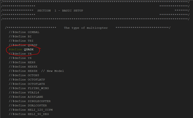
To summarize a bit, it's a really easily configurable software for controlling a lot of different types of drones. I'll be doing a setup for Quad-X which is the one I made.
MultiWii
To set up MultiWii, first, you have to go online and download all of the codes. Once you've downloaded everything, I went with MultiWii 2.3, you get 2 folders MultiWii and MultiWiiConf. MultiWii folder has all of the codes that we need. You have to open the ".ino" file inside that folder. It will open a lot of tabs in Arduino IDE, we then have to navigate to config.h, where we need to make a few changes. For the most part, those changes are either to change a value of some parameter, or to uncomment something.
1. Step - Choosing the drone configuration
2. Step - Defining throttle range
3. Step - Selecting our board
4. Step - PPM configuration
With all of those steps done, our Arduino is set up now with MultiWii. We can now calibrate the accelerometer using the GUI. In the other folder we have when we download MultiWii, we will have a small GUI application for many different types of operating systems. We just have to choose the one that matches ours. There is something to be wary of here.
I couldn't get the MultiWii GUI to start at all when I first downloaded it. Looking at the error file that the GUI created as well searching the error online, I found one person who managed to solve this by changing the version of java on their PC. The person who got it to work that way, did it by changing to java version 1.8.0_202.
I'm using a 64bit Windows 10, to check the java version, open up Command prompt and type java -version
You can download the JRE online, but when you download and install it, you have to give that new path to the computer, I made a new folder for that on hard drive, and set the path with the command:
SET PATH = "file path address to the bin folder inside the folder wheere you've installed it"
I'm not recommending you should do this, this is just something that worked me, but I don't know if it will help everyone.
Testing
To test out everything, I connected the receiver and the flight controller, pin2 - pin2, grounds connected together, and 5V so I can power them using one cable. Before starting up MultiWii, make sure that your flight controller is on a flat surface, then plug in the cable and then turn on MultiWii. If everything is connected properly and working as it should, we should see inputs from our transmitter on the screen, as well as a live demo of the quadcopter orientation. Put the controller somewhere flat and keep it steady, then press the calibrate accelerometer button. This will calibrate the accelerometer and also give you the view of your motors for the simulation. To arm the motors, go down and right for 3 seconds.
5. Testing
With the MultiWii setup complete, we can finally put everything together and get it ready for the first take-off. I of course broke a few things rushing trying to get it flying as soon as possible, so I had to secure the battery with a few additional zip ties. Here is SRD-1 in its first take-off gear.
Lift-off! I was so happy to actually see the drone leave the ground. The landing you see though wasn't intentional. This was running the old IMU, which was causing the controller to shut down after under a minute of runtime, but at least it got down really softly. It was a nice and calm morning for tests like this, the wind picked up during the day as you will see from some of the other videos.
We can see it lifting off again, but due to the wind and the accelerometer not being calibrated properly, it just starts going into one direction. You can also see the legs breaking off at the end, but, that's the good thing about everything being 3D printed, I can just put on new ones.
This time without legs, I'm taking off from my anchor point. Since this is highly experimental and everything still buggy, I've conducted all tests while the drone was still tied to the ground. At the end of the day, it's a 1kg weight just flying around, I don't want it to hurting anyone or just flying away.
And now we get to one of the fatal crashes for today's testing. I'm honestly not sure what went wrong during this take-off. Was it that the gyro messed up, did the arms already break on a previous crash? I'm really not sure, but I had to stop with the testing here because I've broken 2 motors mounts and couldn't continue flying like that for sure. Here is the damage to the arms.
For some reason, I'm having a lot of issues with this filament when it comes to layer adhesion, even though I printed this at a pretty high temperature. I'll try again with this filament, but make the motor mount out of full plastic, to make it more durable to crashes. Not to end a bad note with testing, here are pictures of the drone in the air.
6. SG90 Servo Gimbal
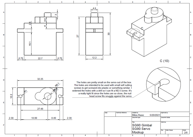
Now we come to the gimbal. One of the main reasons I wanted a drone was for filming purposes, so I thought, why not use the Raspberry HQ Camera. I didn't want to just mount the camera in one position and call it a day, I wanted to make a small gimbal that would give me some control over it. To keep it easy and cheap for the first gimbal, I went with SG90 servos, and designed the gimbal around them and the camera. As for the rest of the project, you can find all of the models free to download here:
Mechanical Design
| {tabbedtable} Tab Label | Tab Content |
|---|---|
Raspberry HQ Camera | This is just a mockup of the Raspberry camera that I used to model the parts around it. |
SG90 Servo | Just like for the Raspberry HQ Camera, this is also a mockup that I used just for the model. |
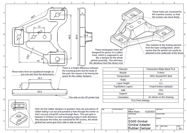
Gimbal adapter with rubber dampers | This is the part that attaches the gimbal to the locking element which is then used to attach the whole thing to the rail of the drone. To try and eliminate the vibrations a bit, I put 2 pieces of rubber tubing as vibrations dampers on every corner of this adapter. |
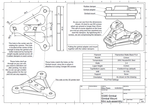
Gimbal mount | Right underneath goes the gimbal mount, which purpose is to attach to the gimbal adapter with the rubber dampers in between. The connection between those 2 will be free to absorb any bigger vibrations, while the connection between other parts of the gimbal and gimbal mount will be rigid. |
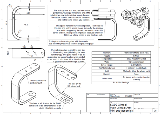
Main gimbal arm | Rather than the whole gimbal just being attached through the axle of the SG90 servo, this arm will give 2 points of contact which will make the whole thing much more stable and stronger, than compared without. |
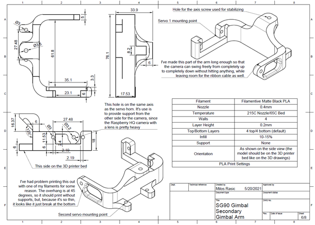
Secondary gimbal arm | The secondary arm rotates inside the primary arm and carries both of the SG90 servos. In the middle of this part, there is an empty area left out for the Raspberry HQ Camera. |
Camera mount | The last part we have is the camera mount. It goes inside the secondary arm and attaches to one of the SG90 servo motors. It has 4 M2.5 holes used for securing the Raspberry HQ Camera to it. |
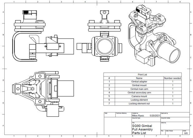
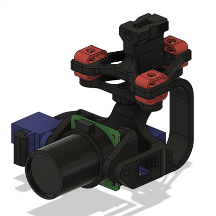
In the end, we end up with an assembly that looks like this:
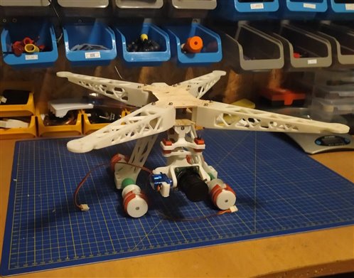
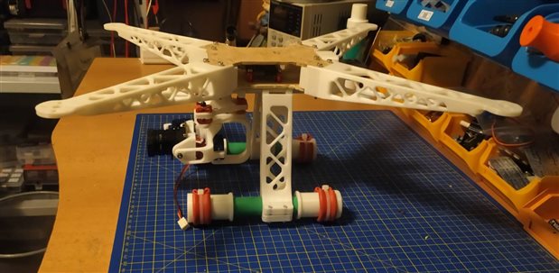
And here is how the real gimbal looks like mounted to the V0 drone:
All of the models for the SG90 gimbal: https://github.com/MilosRasic98/SRD-1/tree/main/3D%20Models/SG90%20Gimbal%20Assembly
Gimbal Test
As one of the first tests for the transmitter-receiver communication with the NRF24 modules, I've made a small test where I would control the position of the servos depending on the joystick. The only troublesome part here is that the Arduino servo library can't be used while we are using the NRF24 library, because of a timer issue. So we can switch to using ServoTimer2 library instead, which uses a different timer.
Raspberry Software
To finish up the gimbal part, I wrote a small script in Python which starts recording using the Raspberry HQ Camera when it detects that a pin is high, and keeps on recording until that pin drops down to zero. It saves every video to a new file based on the date and time of the video recording. One thing I want to add is for it to automatically save to a USB drive. I've made the script run on startup and added LED-s to know when it's ready to start recording and when it's actually recording.
#!/usr/bin/python3


import RPi.GPIO as GPIO
from picamera import PiCamera
import time
from time import strftime


GPIO.setwarnings(False)


LED = 27
LED_ready = 22
Switch = 4


camera = PiCamera()


GPIO.setmode(GPIO.BCM)
GPIO.setup(LED_ready, GPIO.OUT)
GPIO.setup(LED, GPIO.OUT)
GPIO.setup(Switch, GPIO.OUT)


GPIO.output(LED_ready, GPIO.HIGH)


while True:


if GPIO.input(Switch) == 1:
GPIO.output(LED, GPIO.HIGH)
camera.resolution(1920, 1080)
camera.framerate = 25
full_datetime = strftime("%d_%m_%y_%I:%M_p_%S_")
filePath = "/home/pi/Desktop/" + full_datetime + "Video.h264"
camera.start_recording(filePath)

while GPIO.input(Switch) == 1:
time.sleep(1)

camera.stop_recording()

else:
GPIO.output(LED, GPIO.LOW)

GPIO.cleanup()
7. What's next?
The next step is fixing up the drone and getting to fly it more. I've never before had a chance of flying a drone, so I'm still learning a lot. After I dial it in a bit and get more comfortable with it, I'm gonna mount the camera gimbal and the Raspberry on it to see what kind of video I can record with that setup. In the meantime, I'll be conducting some more experiments to see the actual range of the transmitter-receiver combo I made, as well as some range tests for Lora with the Arduino MKR WAN1300 boards. It will be a rainy few days, so I'll have time to print out new arms and design some better legs for the robot. Since this is a part that I think will suffer the most, I'm thinking of using a piece of pipe for each leg as well, so I can have shorter print times for just some smaller adapters.
8. Summary
This was an insanely fun project that turned upside down (both literally and figuratively) just as about I was going to finish it, but looking at it now, I'm glad it happened, now I can reprogram the transmitter and receiver however I want and easily connect them to other electronics. The flight controller needs a bit of work, but I'm positive I'll get it working properly shortly. While it did do a flip in the end breaking its arms and legs, I'm still really happy with how it turned out, and generally that I took off at all considering how little time I had left. This is something I plan on working continuously for quite a long time. You can find all of the models, in both STL and STP formats here: https://github.com/MilosRasic98/SRD-1 . I will publish anything new and update there as well. Thanks for reading my blog, hope you liked it!
Milos
Updated
Just a short update, I've forgot to publish and show the files here for the drone which uses base plates from a different material, so I just want to add that here, since I already have all of the files. The mounting for the arms is same on both drones, the differences are in the base plate, where there is an attachement of a payload bay to print, and the legs are different. Here is how all of those new models look like:
Those are the new parts that need to be printed, as for the base plate, here is the template for cutting:
All of the angles are at 45 degrees to keep it as simple as possible for cutting out by hand. The drone assembly looks like this in this version:
You can find all of these models, as well as the drawing for cutting out the wooden base here: https://github.com/MilosRasic98/SRD-1/tree/main/3D%20Models/Wooden%20Base%20Version
Update 30th of May 2021
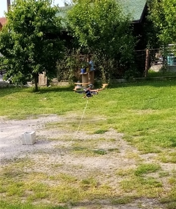
While this Project14 is over, as this is a project I plan on upgrading further and further, I will update this blog with an occasional new flight test video or other relevant information. I printed new legs and took some arms from the white drone, and made a mashup of the 2, to try and fly it again. I've said previously I had problems with the flight controller crashing and so on, and, I suspected the IMU, but upon further testing, I've come to the conclusion that it might be related to one of the RST pins on the Arduino and some short which I can't seem to locate. After cutting those pins off the Arduino completely, I managed to get everything working for another flight test. As there was another car parked in the yard this time, I used a shorter piece of rope for testing.
The last time I was playing around with this drone, I wasn't giving it enough throttle, in the beginning, this time, you can see the drone taking off really good, but you can also see the rope snatching it back as it was a really short rope this time. One of the arms broke after that, but I will get back to testing as soon as I finish the repairs!
Update 3rd of June 2021
This will be just a short update with another magnificent flip. I had a few crashes before this, so I suppose one of the arms gave away during the flight making the robot flip since all of the connections on the controller and receiver still seem good. Only one arm broke, so I'll replace it with another one and try again.
Update 10th of June 2021
As you've probably seen from some of the videos above, this drone got into a habbit of doing all sorts of fun flips and rolls, and then hitting the ground hard. When you look at the video first take off in the blog, you can see the drone taking off great and keeping a really nice and level flight. I've played around with the controller quite a bit along the way, so I thought the main reason was something to do with that (still might be a bit). One thing that crossed my mind a few times, which I ignored, what if one of the ESC-s has gone bad, or one of the motors has gone bad? I already had to take apart one of the motors because of the dust that got inside of it, but I didn't give it a serious thought after that. Because each of these 3D printed arms uses around 40-50g of PLA and takes a while to print, I decided to do a quick redesign, which would let me print out parts faster that are prone to breaking. What does that have to do with the my motor and ESC failure suspicion? When I put the drone back together again (without changing any of the connections between the ESC and the controller), and plugged in the battery, I was greeted with a lot of magic smoke coming out of the motor. So I quickly disconnected the battery to not set anything on fire. Realising then that the probable cause for all of the flips was the bad motor, I thought, why not see if it's maybe the ESC. To try that, I connected the ESC to another motor, and more magic smoke came out, but this time not that much, and the motor still spins okayish, though, I won't be using it for the drone. To make sure everything else is okay, I put the 2 motors and 3 ESC-s I had to test a bit with the load cell, and got pretty good results (There are some variants in max thrust, because one of the already low Lipo voltage at start as well as one of the motors was running for a while and was pretty hot).
I've ordered 2 new motors and another ESC, which should be here before the new deadline, so I hope I can try getting it into the air again in time. There will another update before the new deadline going over some new flights (and fewer flips) hopefully, as well as an update that will go over the new less printed construction, where I've gone and used more of the basic water pipe which I used for the drone legs. Here is a small sneak peek of that.
Update 11th of June 2021 - It finally flies!!!
Hi! This will probably be my last update before the extended deadline for this Project14. As you can see from the name of this update, it flies!!! This morning, the postman delivered the 2 new motors and a new ESC, so I got straight to soldering all of the bullet connectors and putting the whole things together. Before I get to the flight tests, let's take a look at the new and improved design, that you can see in the picture above.
Pipe Construction Design
I broke so many arms due to the drone hitting the ground, the prints would just split between the lines consantly. This was partly because of the filament I was using, the matte black PLA. While it looks amazing, is easy to print, the layer adhesion is just incredibly weak compared to normal PLA. As of writing this, every single part that was printed out of that PLA broke in one way or another. For further improvements, I will be switching to a different kind of PLA. This version of the drone keeps a lot of the parts same as the original version, like the base plates, gimbal, battery tray and so on. The things that have changed are the new arm design, new leg design and I've moved the electronics around a bit and made a few covers to protect the boards.
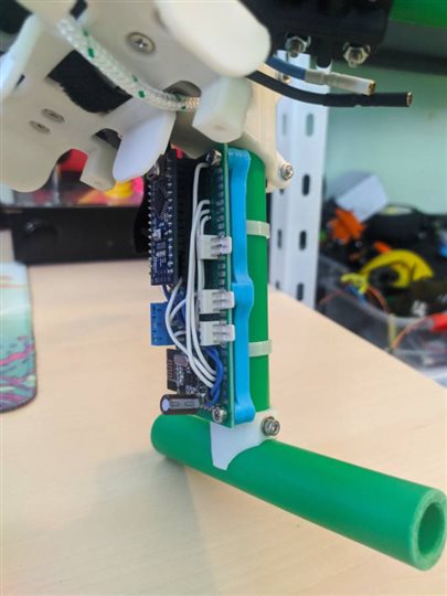
To make the drone a bit lower, I've taken the receiver off the top and mounted it on the inside part of the leg. On the other leg, I've mounted the Raspberry. This was to keep the drone more balanced and to test the mounting system once I get working with the gimbal on the drone.
Controller Assembly
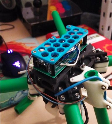
The controller stayed in exactly the same place as last time, the only thing that changed is that on top of it is a 3D printed cover, rather than the receiver. During some rough landings, this cover proved to work great by protecting the electronics from a direct hit.
Receiver Assembly
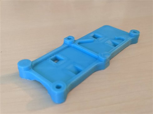
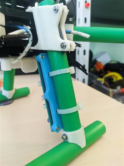
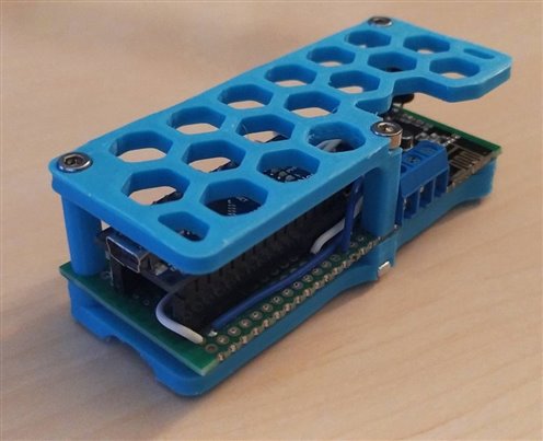
As I've pointed out above, I moved the receiver to the leg of the drone to make it a bit shorter. I designed and printed a 2 piece holder made out of a mount and a cover, which attach to the pipe using 2 zip ties. The board is held together with 3 M3 screws that were used originally.
This part needed supports to be printed and the zip ties need to be put in place before the board is screwed on. Here is how the board goes on the drone.
The cover for this has 3 posts that are used as spacers and a honeycomb mesh on top to keep the weight down. The board probably doesn't need the cover since it's mounted on the inside of the leg, but since it's not a lot of plastic, I decided to print it out.
Raspberry Assembly
The Raspberry mount is designed in the exactly same way as the mount for the receiver, just of course, with dimensions fitting the Raspberry Pi4. To make it a bit slimmer, I cut off the PoE pins and also left a gap for the camera ribbon cable. To be able to use M3 screws here, I had to drill out the holes on the Raspberry a bit.
Arm Assembly
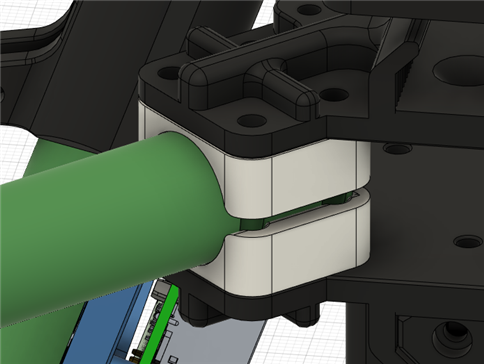
This is the part that went through a major redesign. I made it backward compatible with the arms of the original design, so it can be mixed, which is what I did as I was changing out old arms one by one while experimenting. The pipe attaches to the body of the drone using 2 small parts which are used to clamp in the pipe with the same 4 screws that were used before.
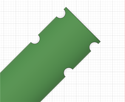
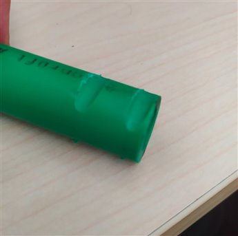
One issue I had to deal with here is that the pipe is too wide for the screw spacing, so I had to cut in shallow grooves into the pipe so that the screws can go through. To do this I just used a rotary tool to take off a bit of material, which worked out great.
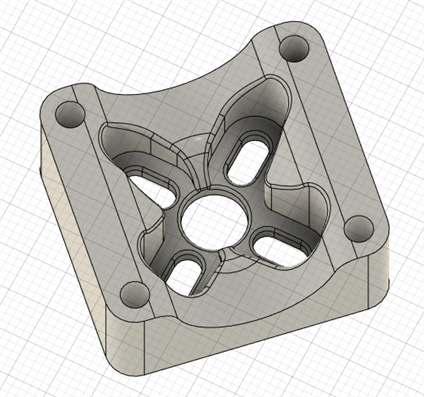
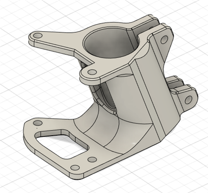
On the other side, the motor is mounted in the same way as the pipe is mounted to the drone body. The motor holder consists of 2 parts, the motor plate, and the motor mount. The motor plate has holes left for mounting the motor itself with inside space left for the screw heads. In each corner, there is a hole left so that the motor plate can be clamped to the pipe using the motor mount. Here is how those parts look.
Leg Assembly
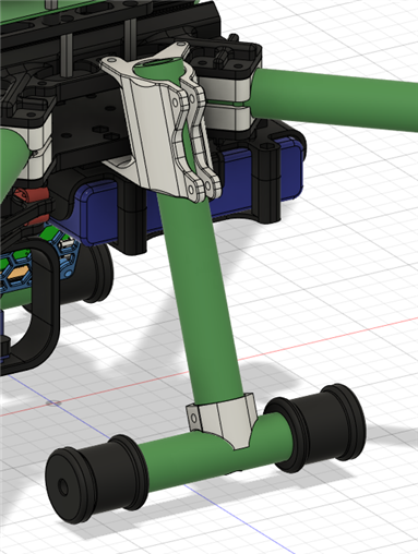
This part went through a major redesign as well, because the old legs kept breaking after the smallest impact. So I just went with the flow of this whole redesign and used the pipe pieces that were used on the plywood version of the drone. Instead of just being mounted at the bottom, these legs are mounted both on top and on the bottom of the drone. For the legs, the leg pipe that's at the bottom is still used. Here is how this whole thing goes together.
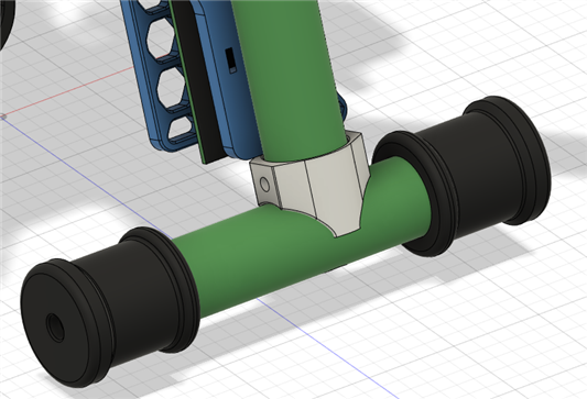
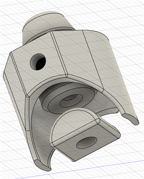
The pipe is fixed in place using 2 M3 screws and nuts. The lower part of the legs consists of a few more pieces. One thing I'm thinking of using here is a simple T joint, but I tried making a slim version with a few 3D printed parts.
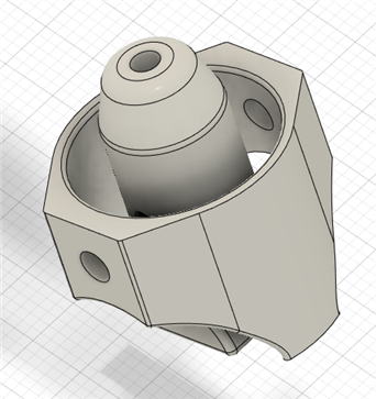
To keep this as slim as possible, one of the parts here needs to be tapped for both M3 screws and M4 screws. Inside the vertical pipe, there is a small piece that has holes for M3 screws which are used to attach it to the vertical pipe, and a center hole for an M4 screw which is used for attaching the horizontal pipe to it with a single screw. To keep that inner piece in place, you can see a simple cover on the outside that has holes for 2 M3 screws. The last part here is a small half circle washer so that the M4 screw has a flat surface to push against when the horizontal pipe is being tightened.
Here is the full leg assembly.
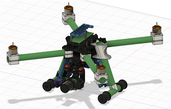
And finally, we have the whole assembly now finished. As for the original version, you can find all of the 3D models on my GitHub here: https://github.com/MilosRasic98/SRD-1/tree/main/3D%20Models%20for%20the%2020mm%20pipe%20version . You can find both STL and STP files, the files come as they are with no guarantee and you are free to do with them whatever you want. Hope you find them useful!
Testing - First Successful Flights
After the assembly, I connected the drone to MultiWii and did all of the calibrations once more to be sure that everything is dialed in. And here are some videos that finally show a successful and stable flight!
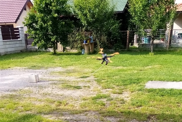
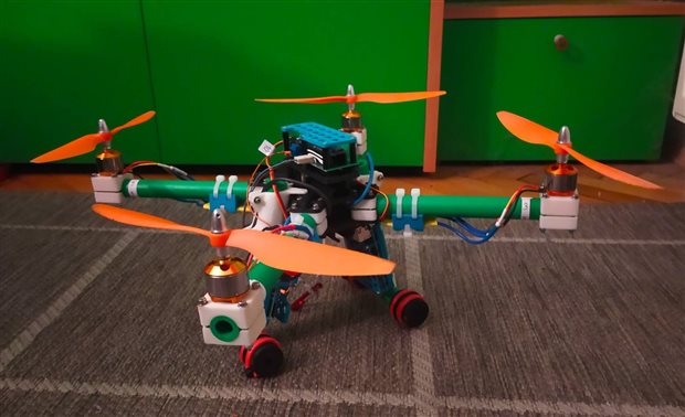
We have flight! After so many different setbacks, it was really rewarding to see it in the air. Some of the landings were a bit rough, but that's completely due to pilot error (lack of skill), but I will be practicing with this thing for sure. I, unfortunately, broke the black base plates on one of the few rougher landings (again that PLA...), so I will do a new design for them that I had in mind and print out them out much stronger for the next version. Once I do that, my plan is to try and record some footage using the Raspberry as well as maybe trying to use Raspberry as an FPV system (Wifibroadcast seems appealing). If you've got this far, thanks for reading through my blog, hope you found it useful or interesting to read. To wrap up for this Project14, here are a few shots of the drone in the air!
16.6.2021 - Short Update
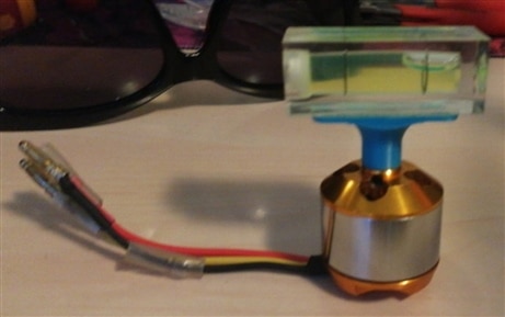
I've added something in the files on GitHub when I was writing this blog, that I've forgotten to cover in the blog by mistake. It's just a simple tool that will make your life easier if you intend to go with the approach of mounting the motors in a way where the mount can freely roate. I've designed a small adapter for a tiny spirit level which goes on the motor, that helps me put the motors vertically. All you have to do is put the drone on a level surface and adjust the mount until the spirit level shows that you're level.






































Top Comments
-

neilk
-
Cancel
-
Vote Up
+4
Vote Down
-
-
Sign in to reply
-
More
-
Cancel
-

milosrasic98
in reply to neilk
-
Cancel
-
Vote Up
+2
Vote Down
-
-
Sign in to reply
-
More
-
Cancel
Comment-

milosrasic98
in reply to neilk
-
Cancel
-
Vote Up
+2
Vote Down
-
-
Sign in to reply
-
More
-
Cancel
Children