


Hello all ! Hope everyone is safe.
This is my entry on the Monthly (March 2022) Element14's Project14's - 7-Segments .
![]()

I've been doing Geocaching a long time. I just love discovering new places, the Nature and solving crazy puzzles. Geocaching can be all that . But, there's another side to it: instead solving other one's caches, create your own, give them a theme, a twist and watch (read) the Geocachers reactions. Since I was a litle, I loved treasure hunts .
I'm from the 80s, and movies like The Goonies just filled one's imagination. Who didn't want to find a pirate's treasure ? Or just like Indiana Jones. Not for the whip, but for the clues, the puzzles, the story.
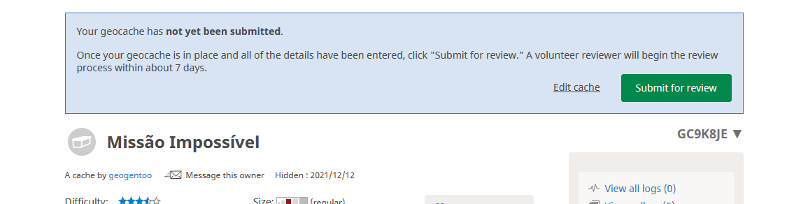
My project is a cache that I've started to develop and build - but it isn't yet in the Nature to be found. I called it Mission: Impossible
The cache
We all know the Mission Impossible movies. For those older (not my time), there was also a TV series in '66 and a TV Series in '88.
On the movies (and the series, but I'm going to concentrate on the movies) they have always a mission, that they need to complete in an impossible time frame and solve any kind of puzzles.
One day, on my email, I received an email from Instructables, with some projects. One of the projects was "The Christmas Box". I found the idea interesting. A multitude of switches, wired in series. To open the box, you need to turn them on, sequentially.
In this case, the first switch is wired to the Arduino 5v PIN. The current is traveling along the switches (while turning them on), until the last one. This last one, the voltage is read in an analog PIN. If the value is not what's expected, the solenoid - that's closing the box - won't trigger to open the lid.
To make this a really fun cache, I've decided to up the ante.
- I've placed some LEDs along the switches. It will be an indication for the Geocacher - when switching the switch, if the LED turns ON, they're on the right track .
- Put a timer - with two single 7-segments display (It was what I had at the time). They need to light all the LEDs - following a path (more on this later) - before the time runs out.
Hardware
For this, we'll going to need
- Arduino Micro (or one you like)
- 15x miniature toggle switches ON-OFF-ON (three positions is more fun)
- 1x miniature toggle switch ON-OFF (to turn the cache on or off)
- 15x round LED 3-6v 6mm
- 1x 7-segment dual display (because I didn't a double, used two singles - more complicated)
- 1x 5v solenoid
- 1x 9v battery adapter
Schematics
Here's all the wiring

The LEds in the schematic are only 3, but just add all the remaining 12 before the last one.
I know it may seem a bit daunting, but it's really not.
Circuit
Here's the start of the wiring


The first switch gets 5v from the Arduino. The middle PIN of the switches is always going to be connected to the next switch. Next, you make a choice. Either you solder it to the top PIN or the bottom one. This will make the switch activate by pushing the switch to top or bottom. They are 3 positions switches. triple the fun ! :)
To make the LED light turn on when putting the switch on the correct position (top or bottom, according to the PIN in which we solder the wire), just wire the positive wire in the middle PIN of the switch. The current will come from it when putting the switch on the correct position. The ground wire to the ground. You keep doing this until the final one.
One thing I've done (and you can see from the black lines in the box, next to the switches) was to create a path. If it was just flipping switches in sequence it wouldn't be as fun.
If you know Geocaching, you can - and should - give a hint to solve the cache. Since I've added a timer, it would take some tries before they could solve the cache in under 40s. It's possible, because the LEDs would indicate that the switch is on, but let's not be too harsh. I want the people to have fun.
On the Geocaching page of the cache (to be updated when cache is published), there's this image:

Using the image as an hint, they will understand the order to flip the switches.
7-Segments display

The 7-Segments display can be of two types - common Anode or common Cathode. Mine are common Anode, meaning all the anodes are connected to VCC and the individual segments are turned on and off by switching power to the cathodes. If it's low, then the segment is turn off and vice-versa.
Here's an excellent learning tutorial on the wiring and the types of 7-segment displays. You just need to know yours.
https://www.circuitbasics.com/arduino-7-segment-display-tutorial/
Basically, each segment of the 7-segments display (single ones. This changes for double or quadruple digits) has a pin that needs to be connected to the Arduino. Since I'm using two single digits, way more wiring needed and the code it's a bit more complicated.
Each segment is labeled from A to G. Each segment (at least for these 7-segments display) has a PIN to connect to the Arduino. For mine, change - to + . (images from Circuit Basics).


To know what PINs to connect to Arduino, check the datasheet.
Code
The code is very straightforward, being the code for the 7-segments the more "complicated" stuff, because I had to use two single digit to make one double digit.
#include "SevSeg.h"

#define readVoltagePIN A1
#define solenoidPIN A2

//#define DEBUG 1
#define DEBUG 0

/*
 * Defined those here, so we can make an animation
 * when cache is openned and show and hide where they
 * get at
 * ie: 11s to end, so 11 wil show and hide
 */
static int i,j = 0;

SevSeg sevseg_1;
SevSeg sevseg_2;

/* declared global so it can be used in another function */
byte segmentPins_1[] = {0, 1, 2, 3, 4, 5, 6};
byte segmentPins_2[] = {7, 8, 9, 10, 11, 12, 13};

void setup() {
  // put your setup code here, to run once:
  byte numDigits = 1;
  byte digitPins[] = {};
  /* byte segmentPins[] = {A, B, C, D, E, F, G} */
  //byte segmentPins_1[] = {0, 1, 2, 3, 4, 5, 6};
  //byte segmentPins_2[] = {7, 8, 9, 10, 11, 12, 13};
  bool resistorsOnSegments = true;

  byte hardwareConfig = COMMON_ANODE;
  sevseg_1.begin(hardwareConfig, numDigits, digitPins, segmentPins_1, resistorsOnSegments);
  sevseg_1.setBrightness(90);

  sevseg_2.begin(hardwareConfig, numDigits, digitPins, segmentPins_2, resistorsOnSegments);
  sevseg_2.setBrightness(90);

  //pins to open cache and check voltage
  pinMode (readVoltagePIN, INPUT);
  pinMode (solenoidPIN, OUTPUT);
  digitalWrite (solenoidPIN, LOW);

  //because we just need this to run once, everything is in setup
  runCache();
  //display animation
  animateDisplay (i, j);
}

/*
 * animate the numbers like in the movies
 */
void animateDisplay (int i, int j) {
  while (true) {
    sevseg_1.setNumber (i);
    sevseg_1.refreshDisplay();
    sevseg_2.setNumber (j);
    sevseg_2.refreshDisplay();
    delay(1000);
    for (int i = 0; i < 7; i++) {
      digitalWrite (segmentPins_1[i],HIGH);
      digitalWrite (segmentPins_2[i],HIGH);
    }
    delay(1000);
  }
}

/*
 * Funcao para ler o pin analogico para
 * verificar se ja acenderam todos os
 * interruptores
 */
int openCache() {
  int vt = analogRead(readVoltagePIN);
  if (DEBUG) {
    Serial.println(vt);
  }
  /*
   * 900 is the minimum value read
   */
  if (vt >= 900) {
    //if we're here, it's openned and we can stop the clock
    digitalWrite (solenoidPIN, HIGH);
    if (DEBUG) {
      Serial.println("Open");
    }
    return 1;
  }
  else {
    digitalWrite (solenoidPIN, LOW);
    return 0;
  }
}

/**
 * Main function to run the cache
 * It goes from 40s to 0s and during that time,
 * will try and see if the there's voltage on A1
 */
void runCache() {
  delay(1000);
  for (i = 3; i >= 0 ; i--) {
    sevseg_1.setNumber(i);
    for (j = 9; j >= 0; j--) {
      int timer = 1;
      sevseg_2.setNumber(j);
      sevseg_2.refreshDisplay();
      sevseg_1.refreshDisplay();
      /*
       * we're testing this here, so the function to open the solenoid
       * won't have to open it only after 1s - this could be what makes
       * they open or not the cache.
       * And we're at 100ms, so 10 times * 100ms is 1s :)
       */
      while (timer <= 10) {
        if (openCache()) {
          if (DEBUG) {
            Serial.begin("Aberto...");
          }
          return;
        }
        delay (100);
        //Serial.println(timer);
        timer += 1;
      }
    }
  }
}


void loop() {
  //loop is empty
}
We start by including the SevSeg library that I'm going to use. You can find it in github and you can install it the same way you install libraries in Arduino - using the library manager.
This library supports common anode or cathode and it's easy to work with.
We define the PINs for the Solenoid and the Analog PIN to read the voltage
#include "SevSeg.h"#define readVoltagePIN A1#define solenoidPIN A2
Next, we define some variables to create a nifty animations
/* * Defined those here, so we can make an animation * when cache is openned and show and hide where they * get at * ie: 11s to end, so 11 wil show and hide */static int i,j = 0;
We declare two variables, one for each display, of the type SevSeg.
Then we define what pins are connected to which display, by declaring two arrays
SevSeg sevseg_1;SevSeg sevseg_2;/* declared global so it can be used in another function */byte segmentPins_1[] = {0, 1, 2, 3, 4, 5, 6};byte segmentPins_2[] = {7, 8, 9, 10, 11, 12, 13};
The setup function
The code for the cache will run all from the setup function. We don't need a loop function. More on this later.
Next, are variables that will define the library behavior and setup
byte numDigits = 1; byte digitPins[] = {}; /* byte segmentPins[] = {A, B, C, D, E, F, G} */ bool resistorsOnSegments = true; byte hardwareConfig = COMMON_ANODE; sevseg_1.begin(hardwareConfig, numDigits, digitPins, segmentPins_1, resistorsOnSegments); sevseg_1.setBrightness(90); sevseg_2.begin(hardwareConfig, numDigits, digitPins, segmentPins_2, resistorsOnSegments); sevseg_2.setBrightness(90);
numDigits defines how many digits our display has. In my case, just the one. If I were to use a dual-digit display, here would be 2 or 4 for a four-digit display.
digitPins array would define to what Arduino PINs the digits wold be connected. This is very dependent on the hardware you have. Since I'm using 1 digit display, this is empty (it needs to be defined).
Next, would the segmentPins (I've declared them above, because need them also elsewhere). This is an array that declares what segments are connected to what Arduino PINs. 7-segments display - get it ?
Read more here. Excellent tutorial and learning
resistorsOnSegments refers to if resistors are connected to the segments or digits.
hardwareConfig referes to if they are common Anode or Cathode.
There are more variables to define (i.e: leading zeros, etc..) but I don't need them, so, not declaring them. Read the library documentation - the Github page - for more information.
Next, we initialize both displays, with all the variables defined and set the brightness.
sevseg_1.begin(hardwareConfig, numDigits, digitPins, segmentPins_1, resistorsOnSegments);sevseg_1.setBrightness(90);sevseg_2.begin(hardwareConfig, numDigits, digitPins, segmentPins_2, resistorsOnSegments);sevseg_2.setBrightness(90);
We then set the PIN mode for the Solenoid and the Analog for the voltage reading. I've set the solenoidPin to low, just in case - we don't want the cache to be open when the Geocacher starts.
//pins to open cache and check voltagepinMode (readVoltagePIN, INPUT);pinMode (solenoidPIN, OUTPUT);digitalWrite (solenoidPIN, LOW);
Next, we call a function to start the cache - ie, countdown timer - and next, an animation.
//because we just need this to run once, everything is in setup runCache(); //display animation animateDisplay (i, j);
This is way we just need the setup function. The runCache() function only exits when the timer gets to 0. If the Geocacher manages to flip all the switches in time, it signals the solenoid to open. If not, it does nothing. If it wants to try again, just turn the cache off and on again.
runCache function
This is the function that controls everything.
void runCache() { delay(1000); for (i = 3; i >= 0 ; i--) { sevseg_1.setNumber(i); for (j = 9; j >= 0; j--) { int timer = 1; sevseg_2.setNumber(j); sevseg_2.refreshDisplay(); sevseg_1.refreshDisplay(); /* * we're testing this here, so the function to open the solenoid * won't have to open it only after 1s - this could be what makes * they open or not the cache. * And we're at 100ms, so 10 times * 100ms is 1s :) */ while (timer <= 10) { if (openCache()) { if (DEBUG) { Serial.begin("Aberto..."); } return; } delay (100); //Serial.println(timer); timer += 1; } } }}
It's just two for loop functions - one controls the dozens (from 3 to 0) and the other the ones (9 to 0).
Because of the refresh (again, two single digit displays), between the for loop for the dozens and the for loop for the ones, we display the dozens, using the SevSeg function setNumber .
On the second loop, we display the ones and refresh both displays.
Inside this for loop, we set a timer. This timer is here so that the cache opens immediately if the voltage at the PIN is high enough. If we don't set this here, this was only checked after each second.
This could work great - unless there's just one second left on the timer . Like in the movies, they all defuse the bomb in the last second - and the timer would end and not cache would open.
The delays, will time 1s for the ones and 1s for the dozens.
In this cache, there's also a checking on to open the cache
if (openCache()) {
This will check another function
openCache function
This function checks the voltage on the analog Pin (The ADC circuit) and reads the value. After some testing, 900 is the minimum value read when all the switches are flipped correctly.
If we get lower, then it means that no voltage is reaching the PIN, hence the switches are not all flipped correctly.
NOTE: This was my way. I'm sure that could be other ways, or this value may be dependent on the battery voltage being full or almost empty. This uses a 9v battery.
If the value is above 900, then, we turn the SOLENOID PIN to high and it retracts it, opening the cache.
Back to the runCache.
If openCache returns 1 - meaning it's opened, we exit the runCache loop() - and back to the setup function. Remember - this function was called from there.
If openCache returns 0, we keep going in the openCache loop until the timer runs out (but the cache never opens).
After exiting the runCache function, we show the animateDisplay function.
animateDisplay function
This function takes 2 arguments - i and j . This are the variables that countdown in the runCache function.
If we exit the runCache function with still time left, i and j will be the time left : i is dozens and j is ones.
If we left the time run out, both will be 0.
In a infinite loop, we display i and j on the 7-digits display. Delay 1s.
After that, we put all the segment PINs on HIGH, making them turn off. Wait 1s and display the digits again...
Here's a video of the cache working
NOTE: Here's the cache page. It's not yet published, you'll received an error. It's been raining and I haven't yet had time to publish it. The cache page is done, but still have to place it .
References
https://create.arduino.cc/projecthub/KVLakshmiSri/00-to-99-on-seven-segment-displays-1ca7e0
https://www.circuitbasics.com/arduino-7-segment-display-tutorial/
-

dubbie
-
Cancel
-
Vote Up
0
Vote Down
-
-
Sign in to reply
-
More
-
Cancel
Comment-

dubbie
-
Cancel
-
Vote Up
0
Vote Down
-
-
Sign in to reply
-
More
-
Cancel
Children