


TL;DR: Debugging a CAN board with PYNQ-Z2's logictools and WaveDrom ->
-> A lot faster than debugging Assembly!
This blog is long overdue, I hope your tea did not get stale in the meantime;) I am finally caught up with all of the university assignments, really starting to believe I was a turtle in the previous life, and dive into the "homework" in between the ongoing exams as much as I can.

As I certainly do not have the creativity of yuricts whose Taylor waves post is a must-read that gave me some genuine giggles, my post is rather related to something from the back of the drawer that has been troubling me for some months now. That is an old unfinished project for a course which had to be scrapped due to the quarantine measures as by that time I was not able to make the project work completely. In short, as a semi-competent student just recently established a foundation of Assembly, I decided to write a PIC18 driver for an MCP25625 (CAN controller + transceiver), for a small PCB which I made to communicate data between a solar racing car and a PC. As you may already expect, but I did not at the time due to my overconfidence, that is quite hard; at the end of the task, I ended up with a little under 1000 lines of Assembly code (now that's honestly a lot for an initially "quick" job). Although stepping in MPLABX through the code and analyzing register values appeared to be working fine, once plugged in the board did not work. I was getting some Woo-doo behavior in that my SPI clock would start clocking only when I bring a hand close to the pin (whaaat?!?) or that the CAN controller seemed to never enter the "Normal Mode". After some time, the board headed into the drawer awaiting better days.
After the first session of the PYNQ-Z2 Embedded Vision workshop, I thought where I could use the "logic analyzer" functionality shown in the webinar after adamtaylorcengfiet's remark on homework examples and this old project came to mind. So today after sweeping all the course work from the table, I got to work on this and the 2 following sessions.
What took me hours of typing and days of checking simulation in MPLABX, took about an hour all together to do in PYNQ. Now that's productivity. I initially wanted to replicate Analog Discovery real-time logic analyzer on PYNQ, but after looking into the API of logictools and its source code, realized it would not be possible to do live display with the methods available in the tools so far. As it was not crucial to the task at hand, simply running the sequence of writing and reading bytes was sufficient for me to check what is wrong with the PCB. Writing out logic for initialization of the CAN controller in PYNQ took 40 lines instead of 1000 in Assembly!!!
msg1 = {
    'signal': [
        ['Stimulus',
            {'name': 'CLK', 'pin': 'D1', 'wave': 'l'+'hl' * 24+'.'+
                                                 'hl' * 24+'.'+
                                                 'hl' * 56+'.'+
                                                 'hl' * 48+'.'+
                                                 'hl' * 24+'.'},
            {'name': 'MOSI', 'pin': 'D0', 'wave': 'l'+'.'*11+'h.'+'l'+'.'*3+'h'+'.'*3+'l'+'.'*9+'h'+'.'*15+'l'+
                                                  '.'*12+'h.'+'l'+'.'*3+'h'+'.'*5+'l'+'.'*7+'h'+'.'*15+'l'+
                                                  '.'*12+'h.'+'l'+'.'*5+'h.l.'+'h.l'+'.'*17+'h'+'.'*7+'l.h'+'.'*7+'l.h'+'.'*3+'l'+'.'*15+'h'+'.'*11+'l'+'.'*16+
                                                  '.'*12+'h.'+'l'+'.'*9+'h'+'.'*3+'l'+'.'*53+'h.'+'l'+'.'*12+
                                                  '.'*12+'h'+'.'*3+'l'+'.'*7+'h'+'.'*5+'l'+'.'*19},
            {'name': 'CS', 'pin': 'D2', 'wave': 'h'+'l'+'.' * 47+'h'+
                                                'l'+'.' * 47+'h'+
                                                'l'+'.' * 111+'h'+
                                                'l'+'.' * 95+'h'+
                                                'l'+'.' * 47+'h'}],
        {},
        ['Data Out',
            {'name': 'Data', 'wave': '4'+'.'*15+'5'+'.'*15+'='+'.'*15+'x'+
                                     '4'+'.'*15+'5'+'.'*15+'='+'.'*15+'x'+
                                     '4'+'.'*15+'5'+'.'*15+('='+'.'*15)*5+'x'+
                                     '4'+'.'*15+'5'+'.'*15+('='+'.'*15)*4+'x'+
                                     '4'+'.'*15+'5'+'.'*15+'x'+'.'*17,
                             'data':['CMD:0x02','ADD:0x60','DATA:0xFF',
                                    'CMD:0x02 (WRITE)','ADD:0x70','DATA:0xFF',
                                    'CMD:0x02 (WRITE)','ADD:0x28','DATA:0x03','DATA:0xDE','DATA:0xC0','DATA:0x3F','DATA:0x00',
                                    'CMD:0x02 (WRITE)','ADD:0x0C','DATA:0x00','DATA:0x00','DATA:0x00','DATA:0x40',
                                    'CMD:0x03 (READ)','ADD:0x0E']}],
        {},
        ['Analysis',
            {'name': 'CLK', 'pin': 'D17'},
            {'name': 'MOSI', 'pin': 'D19'},
            {'name': 'MISO', 'pin': 'D18'},
            {'name': 'CS', 'pin': 'D15'},
            {'name': 'INT', 'pin': 'D16'}]],
        'foot': {'tock': 1},
        'head': {'text': 'MCP25625 - CAN Controller+Transceiver'}
}
The CAN board was intended for use with a 5V IO of a PIC18 so I had to do some "modifications" to the board so the ZYNQ 7020 does not get mad at me and decides to stop working, which all in all looks more like savagery now. I cut power traces to the logic part of the CAN unit and connected them to an unused header pin using a bare copper wire strand (barely visible on the picture) salvaged from a 24AWG multicore wire along with adding a pull-up for a RST pin.

After thorough checking for shorts, the board was connected and the register initialization was carried out. Sweet! the INT line is pulled high and the board waits to be initialized, PYNQ-Z2 is now sending the sequence of commands, addresses and data bytes to set everything up.
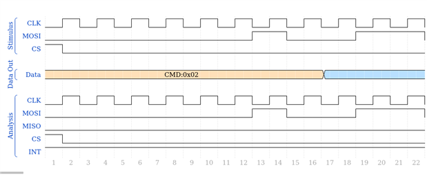
However, having sent the setup bytes, the last transaction read the bytes from the control register on MISO line, which were all 0's indicating the board was not configured. That immediately rose question and I tried sending "SPI" data in mode 1,1 (3) instead of 0,0 (0), which the MCP25625 claims to support both. And what do you know, at the end of the transaction I get the expected 0x40, indicating the CAN controller is in loopback and was configured.
In a matter of less than half a day, I was able to debug the board and find out that my Assembly code from several months ago was correct, but for some mysterious reason, despite of supposedly working in both SPI modes, the CAN controller successfully worked only in mode 3. Having a PYNQ-Z2 as logic analyzer at the time would have been a huge help in figuring out this issue and saving countless hours of headache.
Huge thank you once again to adamtaylorcengfiet, tariq.ahmad and element14 for organizing and supporting this great workshop! I am going to catch up on the other sessions in the coming days too 