


From a spare Arduino and a breadboard to a custom PCB controlling valves, sensors and the full canning cycle
|
Project at a glance • Controller: Arduino Nano • Outputs: four Airtac 4V210-08 electro-pneumatic valves • Sensor: Baumer LBFS liquid level sensor • User controls: power, cycle start/abort, beer enable and CO2 enable • Power: 12 V DC system, with 5V supplied to the Arduino through a buck converter • Final build: a custom PCB designed in EasyEDA and manufactured by JLCPCB |
1. Background and inspiration
Back in early 2025, a friend asked me to help with a home beer canning machine. He had already built the mechanical and pneumatic side. What he needed from me was the control system.
My friend had previously run his own brewery and is also a bit of an inventor. His aim was to get something approaching pub-standard brewing and canning at home. The machine would move cans through the filling area, purge them with CO2, fill them with beer, where they could then be passed on to a separate machine to fit the lids.
My own electronics knowledge came with a slight complication. I studied Electronics and Computing at BTEC level when I was 19. I kept up with the computing side over the years, but most of the electronics had quietly escaped. I had always meant to get back into it one day, and this project turned out to be the excuse I needed.
The brief was simple to describe and rather less simple to build: make one compact, self-contained circuit that could control the whole machine. It had to fit inside a case on the side of the canner and, apart from power, it could not rely on any external wiring or a connected computer.
What the controller had to operate
-
An air-powered arm to move cans horizontally along the line.
-
An air-powered arm to raise and lower the beer and CO2 outlets.
-
A valve to control beer flow.
-
A valve to control CO2 flow.
-
A momentary switch to start a cycle, which I later turned into the emergency abort control as well.
-
Two latching switches so beer and CO2 could each be enabled or disabled for a particular cycle.
- A liquid level sensor
Coincidentally, I had bought a basic Arduino board a few months earlier and had not yet found a use for it. This looked like exactly the sort of job it had been waiting for. The Arduino could hold the program and run independently once installed, so I started by learning what each component needed and testing everything one piece at a time.
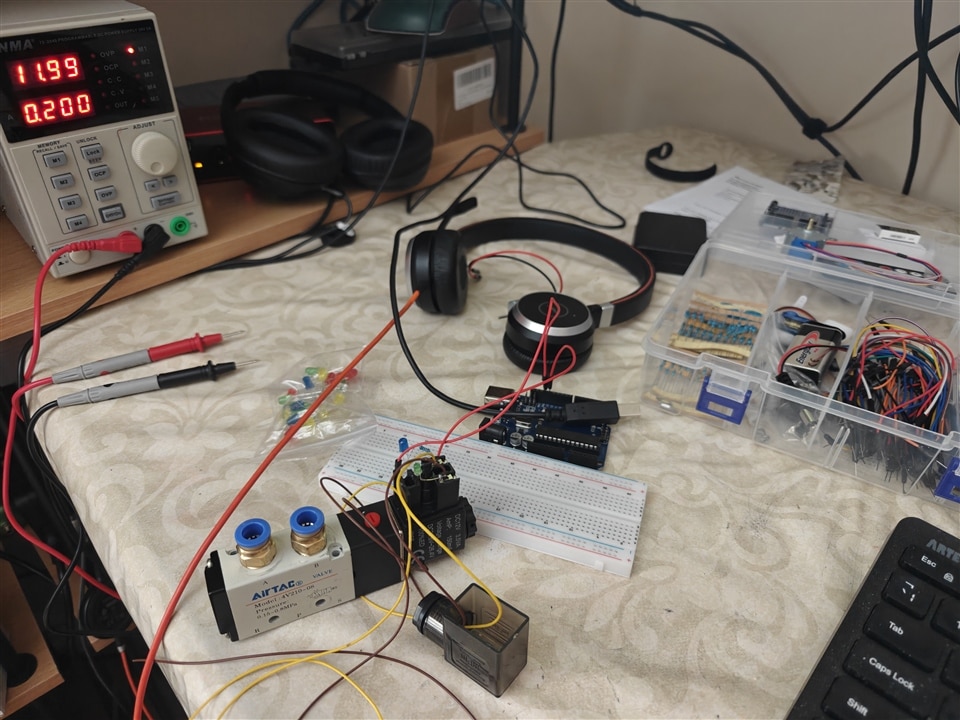
Early bench testing. At this stage I was deliberately testing one component at a time before trying to make the whole machine behave.
2. First challenge: the electro-pneumatic valves
I started with the electro-pneumatic valves because they looked interesting. They are pneumatic valves operated electrically by a solenoid, and they ended up causing more head-scratching than any other component in the project.
The valves were labelled Airtac 4V210-08. The markings on them did not make the supply requirements immediately obvious:
|
Valve markings • DC12V 3.5VA • AmP 150mA • Voltage range: DC21.6V to 26.4V • 100% ED |
That raised the obvious question: were they 12V devices or 24V devices? I searched Airtac's website, but I could not find this exact variant with markings that matched the valves in front of me.
My first circuit used a transistor to switch a valve from the Arduino. I set the bench supply to 12V with a fairly low current limit, uploaded a small test program and heard a very satisfying click. Success. Or so I thought.
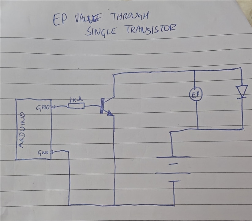
My first hand-drawn idea for switching one electro-pneumatic valve through a transistor.
As I added more valves, the clicks became distinctly less enthusiastic. Eventually I was not sure they were moving properly at all. I took a spare valve and slowly increased the supply voltage. At around 24V it snapped open and closed confidently, and with four valves connected they all worked. At the time, that seemed to settle the matter: I designed the rest of the prototype around 24V. This decision would come back to bite me later.
3. Testing the LBFS liquid level sensor
Next came the Baumer LBFS liquid level sensor. This was a much more expensive and sensitive bit of kit. In our application its job was simple: keep watching the beer level and tell the Arduino when the can had reached the correct fill height so the beer could be shut off.
Unlike the valves, the sensor could feed directly into the Arduino input. I wrote a small test program and used a glass of water on the bench. The Arduino serial monitor changed state as I dipped the sensor into the water and removed it again, which was exactly what I needed to see.
|
|
Wet and dry testing. The blue indicator lights when the sensor is in contact with liquid. |
|
VIDEO | LBFS liquid level sensor test
|
|
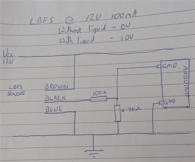 My original wiring notes for the LBFS sensor.
4. One button for start and emergency abort
The main cycle was to be started with a momentary push button. From the beginning, we also knew the machine needed a quick way to stop if something went wrong, for example if a can fell over and was about to be crushed by one of the moving arms.
Rather than add another control, I made the same button do both jobs. If the machine was idle, pressing it started the cycle. If a cycle was already running, pressing it again aborted the process, retracted the filling arm and the can-feed arm, and shut off any beer or CO2 that was flowing.
To make that possible, I wrote the program as a loop that runs constantly, thousands of times a second. The loop, known as a "State Machine" checks the state of the button each run and, if it detects that it has been pressed, it calls the emergencyStop() code:
|
if (!processIsRunning && mainState != MAIN_IDLE) { |
The state machine also handles the physical sequence, including moving the cans, waiting 700 ms for them to settle, lowering the dispensing arm and then carrying out the filling operations.
5. Beer and CO2 override switches
Two latching switches let me enable or disable beer and CO2 independently for each cycle. That means the machine can run with both enabled, either one disabled, or both disabled. It is useful for getting the first can in the line purged with CO2 before beer reaches it, and it also gives us more control when cleaning the system at the end of a run.
6. The neat solution that got very hot
At this point I started wondering whether there was a tidier way to switch everything. My original approach meant using a separate transistor for each output, and I was heading towards seven of them. An integrated driver looked much neater, so I tried a ULN2803.
The ULN2803 Integrated circuit contains eight pairs of Darlington transistors. It features built-in diodes to protect against voltage spikes.
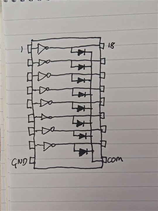 A very rough sketch of a ULN2803, showing the 8 transistors, protected with diodes
With only a few components connected it looked promising. Then I added the fourth electro-pneumatic valve. The ULN2803 decided it had contributed quite enough to the project and retired at a fairly impressive temperature. Lesson learned.

The ULN2803 experiment. It looked like a neat way to replace several separate transistors, right up until it became the hottest component on the bench.
After checking the requirements properly, I went back to individual switching devices and compared IRLZ44N and IRFZ44N MOSFETs. I settled on the IRLZ44N. It was more than I strictly needed, but the final electronics would live in an enclosed space with very little ventilation, so running cool mattered more than shaving a few pence off the parts list.
7. Shrinking the controller
The full-size Arduino was taking up more room than I wanted. I moved to an Arduino Nano, which could sit directly on the final circuit board and still be removed for reprogramming if necessary.
Because I was still working on the assumption that the main machine would run at 24V, I added a buck converter to produce a clean 5V rail for the Arduino. That worked well and gave me one power input for the whole controller rather than a separate supply just for the microcontroller.
8. The stress test and sorting out the power
By now I had a complete breadboard prototype and the software was running. Short tests looked fine, but we had never asked it to do anything like a real production run. So we loaded up 50 cans and let it work.

The full breadboard prototype before the long test run.
At around can 20, the electro-pneumatic valves inside the machine started getting warm. Then warmer. Then hot enough that I was no longer willing to pretend it was probably fine. We stopped the test and I went back to the drawing board.
This was the point where the gap between the electronics I had learned years ago and the electronics I could still remember became rather obvious. I spoke to a friend who designs components for a living. Looking back at my original 12V tests, he pointed out that I had increased the voltage when the valves seemed weak, but I had not increased the available current. He suggested going back to 12V, but with a higher current, where the valves should run much cooler.
Fortunately, that did not mean redesigning everything. The main change was the buck converter. I replaced it with an adjustable unit that could accept roughly 4 to 40V DC and provide an adjustable output, so I could run the machine from 12V and still supply the Arduino with 5V.

Back on the bench at 12 V. This version became the basis for the PCB design.
|
The useful lesson from this part • A single successful click on the bench does not prove a design is ready for repeated operation. • Current limits matter just as much as the voltage setting when testing solenoids. • The 50-can test found a problem that short bench tests had completely hidden. |
9. From breadboard to a real circuit board
Once I was happy with the circuit, the next challenge was getting it off the breadboard and onto something that could actually live inside the machine. I had tried making my own PCBs when I was younger and remembered enough of the experience not to be in a hurry to do it again.
I found that having a small batch manufactured was surprisingly affordable, but first I had to learn PCB design software. I started with KiCad because it is widely used, but I never really got on with the interface. I then tried EasyEDA, which clicked with me much more quickly, so I designed the board there.
I translated the breadboard circuit in a modular way. Each electro-pneumatic valve had its own repeated switching section, then I added the sensor, switches, power conversion and Arduino connections around those blocks.
 The completed schematic in EasyEDA. I built it up in repeated modules so each valve channel could be checked separately.
10. PCB layout: making it serviceable
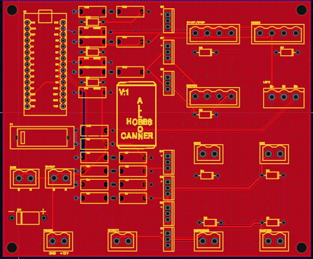
The PCB itself went through a lot of iterations. I wanted more than just a board that worked. If something failed later, I did not want to have to desolder half the machine to fix it.
The Arduino Nano therefore sits in pin headers rather than being soldered permanently to the board. The external wiring uses plug-in connectors instead of wires being soldered directly to the PCB. That makes the controller much easier to remove, reprogram or repair.
|
Final PCB layout in EasyEDA. |
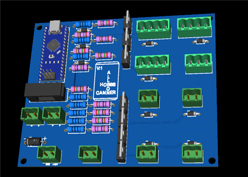
EasyEDA's 3D mock-up of the populated board. |
11. Sending the board away: no undo button
I spent several weeks checking every component, trace and copper pour. This was the first PCB I had designed at this level, and software development had given me a bad habit: if code is wrong, I can edit it and try again. A manufactured circuit board is less forgiving.
Eventually I uploaded the files to JLCPCB. Their checks said the design looked valid, which was reassuring. Then I clicked Pay. That was the moment the project stopped being a drawing on my screen and became something I was going to have to solder together.
The boards arrived remarkably quickly, about five days from China to England if I remember correctly. I used one of the spare boards as a practice run and immediately discovered that the soldering iron tip I had chosen was not ideal for the larger transistor pins. That practice board paid for itself. I changed the tip, moved on to another board and built the final controller.
|
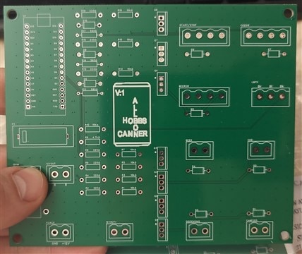
The bare PCB on the day it arrived. |
The finished controller board with the buck converter connected below it. |

12. Into the canning machine
With the controller assembled, I connected every switch, sensor and valve. The wiring looked slightly alarming at first because we had deliberately left generous lengths while developing on the breadboard. Tidying could come later. The first job was to find out whether the board actually worked.

First installation test. The wiring was still deliberately long from the breadboard stage, so elegance had not yet entered the building.
I powered the machine up and the buttons lit as planned. After spending weeks checking the PCB, I pressed the cycle button with rather more nerves than should really be attached to one push switch. By some miracle, it worked.
For the first full test we used water rather than beer. The cans moved along the line, the dispensing arm lowered, CO2 was released for four seconds into one can while water was dispensed into the next, and the fill continued until it reached the LBFS sensor. The machine then stopped the liquid flow, raised the dispensing arm and completed the cycle. The filled can could then be passed to a separate machine to have its lid fitted.
Once I knew the controller was doing its job, I shortened and tidied the wiring and screwed the PCB into its permanent position inside the machine.
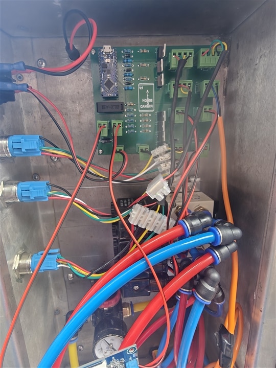
The final controller installed inside the machine. On the left are the power, beer enable, CO2 enable and cycle switches. The pneumatic lines sit below the controller.
|
VIDEO | Full canning cycle
|
13. Where the project stands now
The controller is now installed in the machine and the core process works as intended. It can move the cans, operate the filling head, control the CO2 and beer valves, monitor the liquid level and abort safely if the cycle needs to be stopped.
14. Next improvement: a proper cleaning mode
After five production runs using real beer, one obvious improvement has become apparent. At the end of each run of around 50 cans, the beer and CO2 lines need to be flushed through carefully with cleaning fluid. At the moment, this is more awkward than it needs to be because the CO2 valve only opens for four seconds during each cycle, which means repeatedly pressing the cycle button just to keep the cleaning fluid moving through the system. The next version of the control board will therefore include two additional buttons, one for the beer line and one for the CO2 line. These will bypass the normal timed cycle and hold the relevant valve open continuously for as long as the button is pressed, making the cleaning process much quicker and easier. It is one of those features that seems completely obvious once you have actually used the machine in anger, but somehow never occurred to us during the original design.
15. Project conclusions
For me, the interesting part of the project was not that every idea worked first time. Quite a few of them did not. The confusing valve markings sent me towards 24 V, the ULN2803 got far hotter than it had any right to, and the long canning test exposed a problem that short bench tests had missed completely. Each wrong turn forced me to understand the circuit a little better.
The part I am most pleased with is the move from a temporary breadboard to a compact, serviceable PCB. I started this project thinking I was dusting off some electronics knowledge from a long time ago. I ended it having learned a PCB design package, built a proper controller and, most importantly, watched a machine follow the sequence I had written for it.
|
What I would take into the next electronics project • Stress-test the real load earlier, not just one component on a bench. • Do not choose a part simply because it makes the schematic look tidier. • Design for servicing from the start. Plug-in connectors and a removable Arduino were worth the extra thought. • When a physical PCB is involved, check everything twice. Then check it once more before clicking Pay. |

