


We all have old feature phones lying around in a drawer, destined for e-waste. But recently, I learned about these old devices: many of their LCDs actually use the exact same standard SPI protocols and driver ICs as the hobbyist TFT modules we buy online.
For my latest project, I wanted to put this theory to the test. My goal was to extract an undocumented LCD from a salvaged phone, reverse-engineer its pinout, and make it fully usable with standard microcontrollers (and eventually, my own custom-built MCU).
Here is how I cracked the pinout of a mystery screen using a custom PCB and a software brute-force hack.
The Salvage Operation and Live Probing
Before ripping the phone apart, I needed some baseline data. I opened the phone case, powered up the mainboard, and grabbed my multimeter. By probing the live board while the phone was running, I was able to identify the VCC and GND pins for the display.
Once I knew where power was coming from, I applied a generous amount of flux and used a desoldering wick to safely free the fragile 16-pin ribbon cable from the mainboard. I managed to manually trace out the backlight pins and confirm the ground pins.
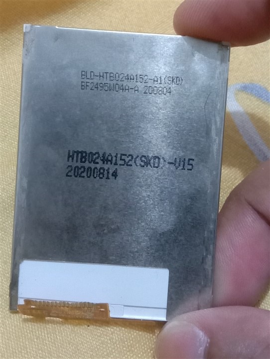
Naturally, my next step was to do what any engineer would do: I checked the part number printed on the back of the LCD and searched for it online. Unfortunately, I hit a complete dead end. There were no datasheets, no pinouts, and no documentation available anywhere. I had a handful of unknown data pins (likely SCK, MOSI, CS, DC, and RST) and was completely on my own to figure out which was which.
Building a Custom Breakout PCB
If you've ever worked with bare LCD ribbon cables, you know they are incredibly delicate and really hard to solder wire directly on it. I didn't want to risk tearing the flex cable while trying to test different pin combinations.
To solve this, I designed and fabricated a custom breakout PCB.
I designed a footprint specifically to accommodate the 16-pin layout of the screen. Using plenty of flux and a steady hand, I soldered the fragile flex cable directly to the surface-mount pads on my board. This gave me sturdy, easily accessible header pins for all 16 connections. Now, the hardware was safe to experiment on.

The "Software Brute Force" Hack
With the hardware secure, I decided to automate the reverse-engineering process using an ESP8266. But to write a brute-force script, I first needed to know what initialization commands to send.
While I didn't have a datasheet, there is a reliable rule of thumb for salvaged phone screens: smaller displays (roughly 1.8 inches) typically use the ST7735 driver, while larger displays (around 2.4 inches with a 240x320 resolution) almost always use the ILI9341. Since my salvaged screen was a 2.4-inch panel, I confidently set up my script to use the standard ILI9341 initialization sequence.
I hooked the wires of my custom PCB up to the GPIOs of the ESP8266 and wrote a custom Arduino sketch to perform a "software brute-force" attack. The concept was simple:
-
I created an array in the code containing all possible pin permutations for the required SPI signals (
SCK,MOSI,CS,DC,RST). -
The code looped through this array, dynamically reassigning the ESP8266's SPI pins on the fly.
-
Every 4 seconds, the ESP8266 would attempt to run a standard LCD initialization sequence and push a solid color fill to the screen.
-
It simultaneously printed the currently tested pin combination to the Serial Monitor.
Visual Feedback & The Eureka Moment
I sat back, watched the Serial Monitor scroll through the permutations, and kept my eyes glued to the blank phone screen.
For the vast majority of combinations, the screen stayed completely lifeless—either staying solid black or displaying a plain white backlight.
Then, something exciting happened: the display suddenly showed random color noise and static!
This static was a massive clue. In SPI displays, random color noise usually means the MOSI (Master Out Slave In) and CLK (Clock) lines have hit the right pins and are actively pushing raw data bytes straight into the frame buffer, even if the control pins (CS/DC/RST) aren't fully synchronized yet to complete a proper init sequence.
I knew I was close. A few cycles later.... The screen transitioned from chaotic color noise into a crisp, solid color fill!
I immediately locked onto the Serial Monitor to capture the pin mapping that was running at that exact second.
The Final Result - Pushing Pixels
With the complete, verified pinout captured, I hardcoded the correct SPI pins into my sketch, and started pushing actual data to the screen using standard ILI9341 libraries.
Seeing full-color image patterns rendering flawlessly on a screen that was destined for the trash just days earlier was incredibly satisfying. Because the screen's pinout is now documented, it behaves just like any off-the-shelf SPI TFT module. I can now wire it up to any standard microcontroller.
The Brute-Force Arduino Sketch
To make this work, I utilized the Adafruit ILI9341 library, but instead of using the standard hardware SPI initialization, I used the Software SPI constructor. This constructor allows you to declare arbitrary GPIO pins for MOSI and SCK.
By placing the constructor inside a 5-level nested loop, the ESP8266 tests all 120 possible permutations of the 5 unknown pins (D1, D2, D5, D6, D7). If you want to replicate this on your own salvaged screen, here is the exact code I used:
-

me_Cris
-
Cancel
-
Vote Up
0
Vote Down
-
-
Sign in to reply
-
More
-
Cancel
Comment-

me_Cris
-
Cancel
-
Vote Up
0
Vote Down
-
-
Sign in to reply
-
More
-
Cancel
Children