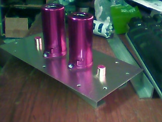
Well, life really sucks a good friend of mine is dying and I have been out of town for the last week or so. And I am going back tomorrow. The Gorilla Brake did not work for the two smaller boxes so pop-rivets will work. The power supply is a nightmare and I will get around to that later. For the time being, I plan on using the power outputs from my beloved Dynakit Stereo 70 which has power take-off sockets on the rear 360vac-0-360vac. I will most likely use both sides of the transformer so that I will have 2 bridges with the center tap being common. The Stereo 70 only uses 6-volt tubes, so I will have to tie them together or use two 12-volt wall warts for the heaters. I lost one of my tube sockets and had to re-order it from eBay. I completed most of the drilling and mounting please see the picture below.
Mounting the tubes was a piece of cake by using a 7/8" hole saw. .I will most likely put a 5-pin DIN female connector on one rear end for power. The other side has blue tube shields and black RCA jacks.
I will be using a one-pair shield wire for the tube heaters. I will also have my output gain controls on the rear by the output sockets. Also on the rear, there is a 5-pin female DIN socket as well, which can be used for a USB audio stream for recording, etc.
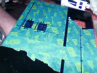
For the layout, I used some basic tools, a good speed square, Permanente Markers by Milwaukee, a ruler, and blue painter's tape. The two black squares are for aux power. As you can see there is an auxiliary power supply that provides soft-start power. It currently provides 12vdc which powers the main relay on the PCB and a 9vdc 3 lead regulator for the Arduino. I will also have to add a voltage doubler to get the 24vdc for the bypass resistors for startup.
In recap on the power supply when finished I will be using an SSCR turning on at the peak voltage also the bypass relay will be energized with a resistor limiting current flow to about 1 amp after about 2 or 3 seconds I can release the relay and short out the resistor. So both right and left amps were laid out the same I took some duct tape and taped them together so I just need to layout it out and drill it once. I did not need to use painter's tape on them as one side had a thin plastic film on it.
SOFTWARE OVERVIEW:
- Arduino wakes up.
- turns-on lamp (power)
- Energize all three bypass relays via optocouplers.
- Start voltage monitor (looking for Vmax!)
- Enter Loop. // for( circuit = 0; circuit < 4; circuit++)
- when Vmax found turn-on SSCR(circuit)
- wait for n seconds.
- turn-off relay(circuit)
- turn-on lamp(circuit)

