


This blog post is intended for Project14 - 'Back to Analog'.
ooops... I think I missed the deadline :-(
When I started this project, I posted a status update and 14rhb suggested to share it into the 'Back to Analog'. Unfortunately I forgot and then noticed it again at the end moment. However, It's not a fully completed project, but I made quite a good progress, and would like to share it in this post.
Intro:
As the name says... in this project I'll try to 'hunt' the 'heart beat pulses' noninvasive using optical method, called PPG [photo plethysmography or light plethysmography].
About the Theme:
As this post is for 'Back to Analog' , the project should be developed using analog modules / components like amplifier ckt.
The basic goal of this project is to explore the design considerations of working with transimpedance amplifier which amplifies input current into voltage. Photo plethysmography is a real life practical application of transimpedance amplifier to amplify photodiode signal.
Photo plethysmography:
"Photoplethysmography (PPG) is a simple and low-cost optical technique that can be used to detect blood volume changes in the microvascular bed of tissue. It is often used non-invasively to make measurements at the skin surface. The PPG waveform comprises a pulsatile ('AC') physiological waveform attributed to cardiac synchronous changes in the blood volume with each heart beat, and is superimposed on a slowly varying ('DC') baseline with various lower frequency components attributed to respiration, sympathetic nervous system activity and thermoregulation. Although the origins of the components of the PPG signal are not fully understood, it is generally accepted that they can provide valuable information about the cardiovascular system."
-source: https://www.ncbi.nlm.nih.gov/pubmed/17322588
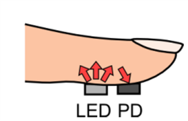
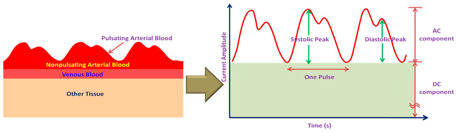
The working principle is pretty simple. A red LED is used to pass light through finger tip and a photodiode is used to receive the reflected light. This contains both the DC and pulse AC components in terms of photo-current. A transimpedance amplifier converts the signal into voltage and amplifies it. Filters are used to get rid of the DC component and the remaining AC component is further amplified to observe using oscilloscope or send to PC using a DAQ system. The PPG signal represents the heart beat, which can be captured at finger tip and takes a small time gap. A simultaneous comparison of ECG and PPG explains the relation and time gap between arrival.


**images are collected from internet [https://www.comm.utoronto.ca/~biometrics/PPG_Dataset/ ]
Project Description:
Block Diagram -
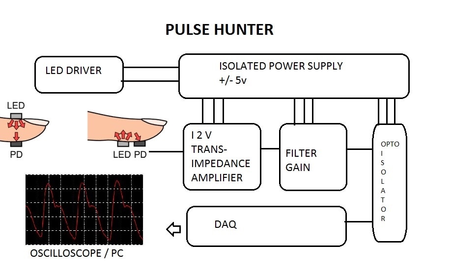
Key Analog Modules -
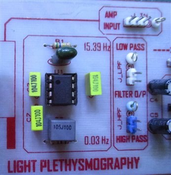
- Transimpedance amplifier
- Basic High and Low Pass filters
- Optical Isolation
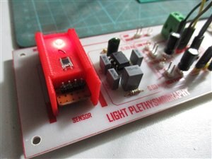
Sensor-
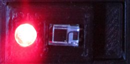
The sensor module consists of a RED LED and photodiode. To drive the LED at constant ~22mA, a LM317 based simple driver ckt is used.
However, the intensity can be varied using an onboard potentiometer.

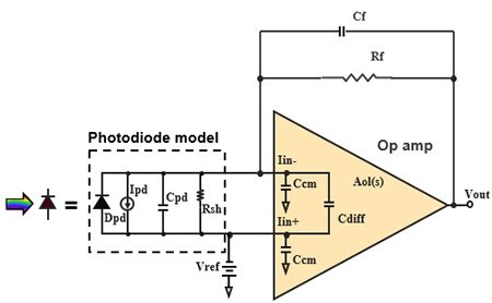
Transimpedance Amplifier and signal conditioning-
The TIA converts the photodiode’s current output signal to a usable voltage level. The implementation of this current-to-voltage conversion consists of a photodiode, an amplifier and a resistor/capacitor feedback pair.


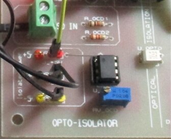
Optoisolator -

Power Supply-
An isolation power supply is used to reduce the mains 50Hz noise. It also converts the single 5v supply into dual +/-5v which is used to the operate the amplifiers in dual supply mode.
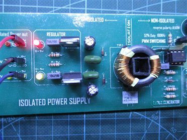

however, isolation circuitry is not necessary in this case, if battery power is used.
Output-

using oscilloscope
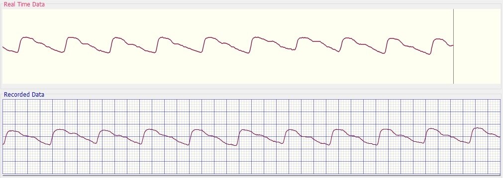
using a DAQ system and software developed by Department of Biomedical Physics and Technology, University of dhaka
This is the brief post on the update of the project. I'll post the detail circuit operation and a little more background study soon.
I'll also try to cover the design considerations of working with Transimpedance Amplifier.
Upcoming feature:
Next to this project I'll process the signal using a microcontroller to show the PPG output on a TFT [320x240] display and calculate heart beat rate from it.
Top Comments