element14 Community
element14 Community
    Register Log In
  • Site
  • Search
  • Log In Register
  • About Us
  • Community Hub
    Community Hub
    • What's New on element14
    • Feedback and Support
    • Benefits of Membership
    • Personal Blogs
    • Members Area
    • Achievement Levels
  • Learn
    Learn
    • Ask an Expert
    • eBooks
    • element14 presents
    • Learning Center
    • Tech Spotlight
    • STEM Academy
    • Webinars, Training and Events
    • Learning Groups
  • Technologies
    Technologies
    • 3D Printing
    • FPGA
    • Industrial Automation
    • Internet of Things
    • Power & Energy
    • Sensors
    • Technology Groups
  • Challenges & Projects
    Challenges & Projects
    • Design Challenges
    • element14 presents Projects
    • Project14
    • Arduino Projects
    • Raspberry Pi Projects
    • Project Groups
  • Products
    Products
    • Arduino
    • Avnet Boards Community
    • Dev Tools
    • Manufacturers
    • Multicomp Pro
    • Product Groups
    • Raspberry Pi
    • RoadTests & Reviews
  • Store
    Store
    • Visit Your Store
    • Choose another store...
      • Europe
      •  Austria (German)
      •  Belgium (Dutch, French)
      •  Bulgaria (Bulgarian)
      •  Czech Republic (Czech)
      •  Denmark (Danish)
      •  Estonia (Estonian)
      •  Finland (Finnish)
      •  France (French)
      •  Germany (German)
      •  Hungary (Hungarian)
      •  Ireland
      •  Israel
      •  Italy (Italian)
      •  Latvia (Latvian)
      •  
      •  Lithuania (Lithuanian)
      •  Netherlands (Dutch)
      •  Norway (Norwegian)
      •  Poland (Polish)
      •  Portugal (Portuguese)
      •  Romania (Romanian)
      •  Russia (Russian)
      •  Slovakia (Slovak)
      •  Slovenia (Slovenian)
      •  Spain (Spanish)
      •  Sweden (Swedish)
      •  Switzerland(German, French)
      •  Turkey (Turkish)
      •  United Kingdom
      • Asia Pacific
      •  Australia
      •  China
      •  Hong Kong
      •  India
      •  Korea (Korean)
      •  Malaysia
      •  New Zealand
      •  Philippines
      •  Singapore
      •  Taiwan
      •  Thailand (Thai)
      • Americas
      •  Brazil (Portuguese)
      •  Canada
      •  Mexico (Spanish)
      •  United States
      Can't find the country/region you're looking for? Visit our export site or find a local distributor.
  • Translate
  • Profile
  • Settings
Circuit Prototype Techniques
  • Challenges & Projects
  • Project14
  • Circuit Prototype Techniques
  • More
  • Cancel
Circuit Prototype Techniques
Blog P14 Prototyping Techniques: Attempting to Measure Op Amp Open-Loop DC Gain
  • Blog
  • Forum
  • Documents
  • Events
  • Polls
  • Files
  • Members
  • Mentions
  • Sub-Groups
  • Tags
  • More
  • Cancel
  • New
Join Circuit Prototype Techniques to participate - click to join for free!
  • Share
  • More
  • Cancel
Group Actions
  • Group RSS
  • More
  • Cancel
Engagement
  • Author Author: jc2048
  • Date Created: 14 Mar 2022 1:23 PM Date Created
  • Views 8488 views
  • Likes 14 likes
  • Comments 8 comments
  • analog design
  • op amp
  • prototyping
  • circuitprototypingch
  • circuitprototypetechniques
  • jc2048
Related
Recommended

P14 Prototyping Techniques: Attempting to Measure Op Amp Open-Loop DC Gain

jc2048
jc2048
14 Mar 2022

As an experimenting blog, this one was a bit of a failure, but I can at least use it to show the
prototyping technique that I'm most fond of.

As a guide, I'm using an Analog Devices article [1]. This suggests the use of a second op amp to servo
the first. Sounded good in theory but didn't work too well for me in practice. Here's what they propose

image

With the switch in the position shown the auxiliary op amp keeps the output of the DUT around 0V, give or
take a small offset of a few tens of uV. With the switch set to 1V the DUT output will have to move to 
-1V to keep the centre of the R4/R5 divider at 0V. The change in voltage at the output of the aux op amp
between those two states is then 1001x the change at the input to the DUT and the gain can then be worked
out as the ratio of the change at the output to the change at the input. Simple! As if...

I don't have a 5uF capacitor but I do have a 10uF one so I'll use that and change the resistors to 100k
to keep the integrator time constant about the same. For the auxilliary op-amp I'm going to use an OP27.

Here's the board I'm going to build on.

image

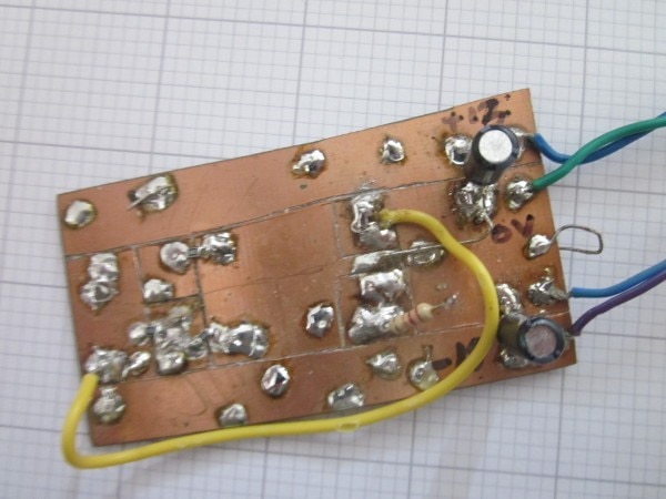
As you can see it's recycled from some other experiment. The cutting between the pads was done with a
craft knife.

Here's an upside-down turned-pin IC socket showing how I place the decoupling capacitors underneath
between the supply pins with the excess lead then being the supply connection down to the pcb.

image

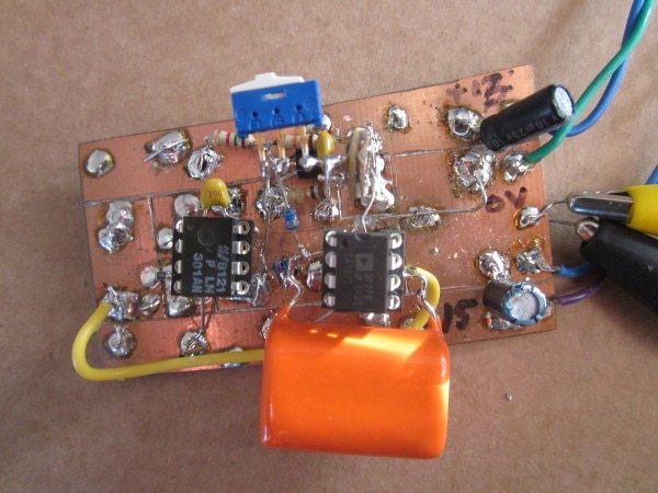
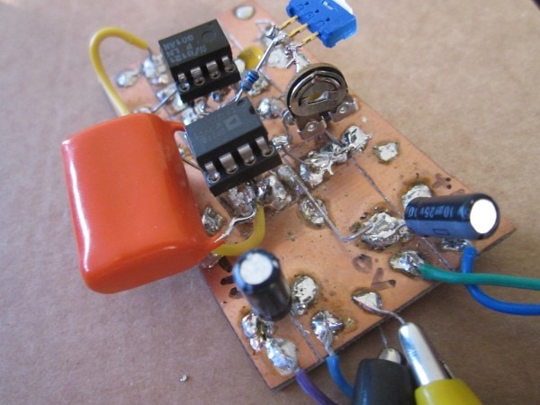
I won't go through the build step-by-step, but here are some pictures of the end result

image

image
image
image

A few tips from my experience so far of building boards like this:
1/ It's worth using a continuity setting on a multimeter to check that all the separate pads really are
separate. It's very easy to end up with a sliver of copper joining areas that shouldn't be joined.
2/ I use a magic marker pen to write on boards. Particularly things like supply voltages which would do
the most damage if subsequently connected wrongly.
3/ Large areas of copper will obviously need a soldering iron with a reasonable heat capacity if you're
going to solder to them. I generally manage ok with a 60W Weller iron and a fairly large 3.2mm chiesel
bit.
4/ For test points for probes, rather than a single wire sticking up I prefer to form a wire into a
triangle or square shape. It's more stable and you're less likely to have an accident with a probe tip or
ground clip shorting something else.
5/ Parts don't have to sit the conventional way up. When wiring directly to the pins of DIL ICs, it often
works better having the part inverted. In this case I can't do that because I wanted to be able to swap
both devices and had to use sockets.
6/ I tend to mix conventional and smd parts for the passives. Sometimes it's convenient to use
(reasonably large) smd parts between pads, sometimes it makes more sense to use conventional parts as
'bridges'.
7/ I've noticed that bright orange capacitors look really cool in photographs.

So does my circuit work? Short answer: no. Here's the output of the DUT

image

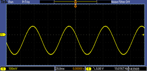
It oscillates nicely. Quite an acceptable sinewave really. With the integrator pole and the compensation
pole for the DUT fairly close together, it was always going to be a bit difficult. It doesn't oscillate
in the simulator (which is a good lesson in how you can't always rely on simulation with analogue
circuits - though, to be fair, they don't expect you to be doing design with a part operating open-loop),
but that doesn't help me with the real thing. Adding some resistance (680R) in series with the
integrator capacitor got it stable, but that then led to another problem.

image

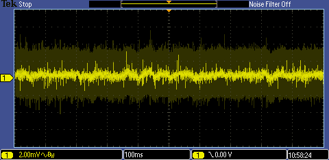
That's the output of the DUT and is the amplified low-frequency (1/f) noise from the op amp input.
Here is the output of the integrator (on AC, so we don't see the -60mV or so of dc offset, just the variation of it).

image

Whilst the integrator removes the very low frequency part and stops the output of the DUT from walking
too far away from zero, it can't deal so well with the somewhat higher frequency 1/f noise and that means
the small change I'm trying to measure is hidden within the meandering value I see on the meter.

There's also a further problem in that the offset voltage of the DUT seems to change with temperature as
the part heats and that seems to have a very long time constant. All a bit frustrating. Do I try and
refine this, or do I give up and try a different technique?

Just realised I need a video to enter the competition. This gives an idea of how the output of the integrator meanders around. This is actually from a later experiment with an OP27, where the noise that's driving that change is less, but it shows the problem with doing accurate measurements using this method.

You don't have permission to edit metadata of this video.
Edit media
x
image
Upload Preview
image

[1] Simple Op Amp Measurements. James M. Bryant.
Analog Dialog, Volume 45, Number 2, 2011.
https://www.analog.com/media/en/analog-dialogue/volume-45/number-2/articles/volume45-number2.pdf

If you found this interesting and would like to see more blogs I've written, a list can be found here:
/members-area/b/blog/posts/jc2048-blog-index-new-version

  • Sign in to reply
  • jc2048
    jc2048 over 3 years ago in reply to dougw

    I had a go with an OP27 and, as you predicted, it was easier to measure than the LM301, though there's still enough movement of the meter readings for this to all be a little approximate.

    That gave me an open-loop dc gain of 3,994,615 (132dB), which is a good bit more than the datasheet typical figure of 1,500,000.

    • Cancel
    • Vote Up 0 Vote Down
    • Sign in to reply
    • More
    • Cancel
  • jc2048
    jc2048 over 3 years ago in reply to dougw

    The key is to change the attenuation back to the DUT. That increases the change whilst leaving the noise that walks the meter reading around roughly the same.

    Unfortunately, it's not possible to go too far with that - my worst offset part now has the integrator output at
    -8.5V to accommodate the offset. Of course, with the 301, I could add the offset trim, so there is a way around that, but I think I've done as much here as makes sense. Whilst this gives some indicative results and was interesting to experiment with, I don't think I have the skill to turn it into an accurate measurement technique.

    • Cancel
    • Vote Up 0 Vote Down
    • Sign in to reply
    • More
    • Cancel
  • jc2048
    jc2048 over 3 years ago

    I took the advice of Shabaz and increased the amount of attenuation from the integrator output to the input of the
    DUT. Rather than increase the 100k further, I decreased the 100R resistors to around 9.6R by putting 10R resistors in
    parallel with them (it was easier to do that than pull the SMD 100R resistors off the board). That gets a larger
    swing at the integrator output for the 1V change and gives me something I can at least measure, if not very
    accurately. I had to increase the resistance in series with the integrator to get it stable for all four of the parts
    I was testing. Take these figures with the proverbial pinch of salt, but that gets me measured gains of 944k
    (119.5dB), 1039k (120.3dB), 692k (116.8dB), and 577k (115.2dB).

    This is what the original datasheet showed for typical figures (I'm measuring with 15V supplies), so they're in the
    right ballpark, though somewhat high.

    image

    • Cancel
    • Vote Up 0 Vote Down
    • Sign in to reply
    • More
    • Cancel
  • dougw
    dougw over 3 years ago

    This brings back some memories of a circuit I designed with an amplification of 1 million. I also used OP27s because of their low noise. I had to use low value resistors and multiple stages to minimize resistor noise. Can you just reduce all resistor values by a factor of 10? Maybe try an OP27 as the DUT just to see if you can get better results from a low noise amp. You could also try running it at as cold a temperature as possible because the noise is also lower at lower temperatures.

    • Cancel
    • Vote Up 0 Vote Down
    • Sign in to reply
    • More
    • Cancel
  • jc2048
    jc2048 over 3 years ago in reply to shabaz

    The general circuit idea is intended as the basis for various tests. The integrator keeps the average output of the DUT at zero, but allows it to move at higher frequencies for doing ac tests. The cap needs to be large to have the cut-off down at a few Hertz. When they did this, 5uF would have been about the largest sensible value for a film capacitor and it makes for reasonable currents in the resistors.

    Although that article was published 2011, I imagine that it was based on something they were doing in the lab back in the 70s and the original probably used physical switches. I can't believe AD was testing op-amps like this in 2011. But, yes, you could drive it with a (very slow) waveform. Measuring the levels accurately to do the gain calculation would become more difficult.

    I think you're right: the attenuation could be increased and that would probably be enough to lift the change out of the noise and get me a reading of some sort, so I might quickly try that later.

    • Cancel
    • Vote Up 0 Vote Down
    • Sign in to reply
    • More
    • Cancel
>
element14 Community

element14 is the first online community specifically for engineers. Connect with your peers and get expert answers to your questions.

  • Members
  • Learn
  • Technologies
  • Challenges & Projects
  • Products
  • Store
  • About Us
  • Feedback & Support
  • FAQs
  • Terms of Use
  • Privacy Policy
  • Legal and Copyright Notices
  • Sitemap
  • Cookies

An Avnet Company © 2025 Premier Farnell Limited. All Rights Reserved.

Premier Farnell Ltd, registered in England and Wales (no 00876412), registered office: Farnell House, Forge Lane, Leeds LS12 2NE.

ICP 备案号 10220084.

Follow element14

  • X
  • Facebook
  • linkedin
  • YouTube