Another attempt at measuring the open-loop dc gain of an op amp, this time using the 'false
summing-junction' method. The idea for this one came from a TI document comparing different
approaches to testing op amps[1].
Before doing it for real, with a circuit on a breadboard, I thought I'd give it a try in a
simulator. It should work ok, though the figure we'll get for the gain will simply be whatever has
been set in the model (which is kind of interesting in itself if we have a complicated model that we
can't make head nor tail of).
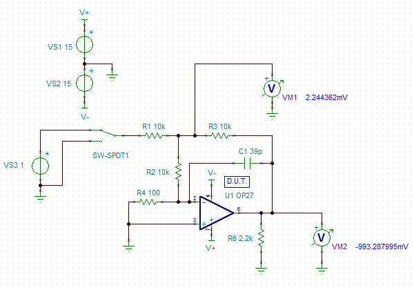
Here is the basic circuit, with an OP27 as the device being tested. The false summing-junction is
the node between R1, R2, and R3, and is being measured with VM1. Because of the potential divider
made up of R2 and R4, the voltage measured at the false junction will be 101x the voltage at the
actual inverting input of the amplifier. The switch simply changes the voltage at the input between
two different values and we can then calculate the gain from the change in voltage at VM1 and the
change in voltage at VM2, the output of the op amp. Notice that the actual input voltage doesn't
affect the calculation, so precision isn't needed there: it just has to be constant whilst the
circuit settles and the measurement is made and of a resonable size that the changes can be
reasonably measured.
Here are some measured simulation voltages. First with the input set to 0V.

Now with the input set to 1V.

The gain, A = 101 * delta(VM2)/delta(VM1)
Which I make 919,988 for the OP27 model.
I then adapted the board that I'd used for the previous experiments and had a go with a physical
circuit. I quickly discovered that I had the same problem as with the previous method - the voltage
I was measuring at the false summing-node was being walked round by the amplified low-frequency
noise. This time, I dealt with that with some filtering of the voltage at the false summing-node.
This is the breadboard circuit:
The 1M/10uF filter calms it down enough to get a moderately sensible reading (that only works
because my Fluke 8808A has an input impedance of >10G on DC voltage ranges of 2V and below, so
doesn't affect the reading in the way that a 10M input would do), though the longish time-constant
means waiting for it to settle before taking a reading. The output is less critical because it
changes by about the same as the input step (ie a big change) and the low impedance of the op amp
output can drive any old meter with reasonable accuracy.
Here's the board, with probes attached, outside of the tin can I screen it with.
Initially I was seeing gains of between 2 and 3 million, but after leaving it for about a quarter of
a hour it had settled down and I was then measuring a more consistent figure of around 1.8M (125dB).
The offset voltage at the DUT input initially increased but then turned around and eventually ended
up below the value it had started with (2.7uV, up to 2.9uV, and then back down to 2.2uV).
It's all very difficult and I don't think I'll arrive at anything more precise with the equipment
I've got and the amount of effort I'm prepared to put into it. Fortunately, it doesn't matter too
much when you're designing with the devices.
[1] https://e2echina.ti.com/cfs-file/__key/telligent-evolution-components-attachments/00-52-01-00-00-09-63-55/_5E00_Op_2D00_Amp-Test-2008_5F00_04_5F00_23_5F00_0900_5F00_3_5F00_DavidBaum.pdf
[2] /challenges-projects/project14/circuitprototypetechniques/b/blog/posts/p14-prototyping-techniques-attempting-to-measure-op-amp-open-loop-dc-gain
If you found this interesting and would like to see more blogs I've written, a list can be found
here: /members-area/b/blog/posts/jc2048-blog-index-new-version
