


Introduction
Now that I've passed the design-a-PCB-and-get- it-made phase, I've been toying with the idea of making my own reflow oven. So I took the step and did what many others have done - I bought a cheap toaster oven. I even purchased an off-the-shelf reflow oven controller unit from another maker on Tindie (details of the controller unit can be found on their GitHub page: https://github.com/UnexpectedMaker/ReflowMaster).
That was well over a year ago. The problem was, while waiting for the arrival of the controller unit, I discovered that the toaster oven is perfect for reheating left over pizza slices and thus shelved that idea of repurposing the toaster oven.
Then our local supermarket had slow cookers on special offer for less than $15. This caught my eye as these were much cheaper than toaster ovens and it used way less energy (150W versus circa 1500W for a toaster oven). So, even though I could readily see that a slow cooker would not reflow a PCB correctly, if at all, straight out the box, I was nevertheless optimistic that with a little a bit of engineering/hacking I could repurpose this slow cooker for reflow. So I went ahead and bought one.

Measuring what needs to be controlled
The first thing I needed to do was understand the temperature profile of the slow cooker. For that I needed to set up a test apparatus and set up a means to measure and log temperature.

As Element14 had sent me an MKR Therm ShieldMKR Therm Shield from a previous Arduino competition, I decided to purchase some 1M K-Type thermocouples (temperature range up to 400 ℃) and use that shield with my MKR1000 boardMKR1000 board. I then added in a TFT screen to show me the temperature values and some other profile info, and I was good to go with my temperature measurement tests.

The Arduino code was fairly straightforward thanks to the Arduino MKR Therm library. I crafted the code so that it samples every second.
/*
  MKR THERM Shield - Read Sensors

  This example reads the temperatures measured by the thermocouple
  connected to the MKR THERM shield and prints them to the Serial Monitor
  once a second.

  The circuit:
  - Arduino MKR board
  - Arduino MKR THERM Shield attached
  - A K Type thermocouple temperature sensor connected to the shield

  This example code is in the public domain.
*/

#include <Arduino_MKRTHERM.h>
#include <SSD1283A.h>                               //Hardware-specific TFT library
#include <Fonts/FreeSansBold12pt7b.h>               // From the Adafruit GFX library

#define CS            6                             // Chip Select SPI pin
#define RST           7                             // Reset pin
#define A0DC          5                             //
#define LED           -1                            // My LED backlight is hard-wired to VCC, hence -1

// Some TFT display colours
#define BLACK         0x0000
#define BLUE          0x001F
#define RED           0xF800
#define GREEN         0x07E0
#define CYAN          0x07FF
#define MAGENTA       0xF81F
#define YELLOW        0xFFE0
#define WHITE         0xFFFF

#define MA_ARRAYSIZE  (5u)

const uint16_t  SAMPLEINTERVAL = 1000;

uint32_t t_int = 0;

float Tval = 0.0;                     // Thermocouple temperature value
float Pval = 0.0;                     // Previous temperature value
float Pave = 0.0;

uint8_t RCval = 0;                     // Defines the reflow Characteristics Profile into "zones": 1 = PREHEAT, 2 = SOAK, 3 = REFLOW, 4 = COOLING

float TDMave[MA_ARRAYSIZE] = {0.0};    // Keeping track of temperature difference. This allows us to calculate a moving average
uint8_t TDi = 0;                       // The index for TDMave
bool TDMfull = false;                  // A bool to determine if ready to calculate the Mave

uint16_t  tCntr = 0;                   // A counter to keep track of the temperature profile


SSD1283A tft(/*CS=*/ CS, /*DC=*/ A0DC, /*RST=*/ RST, /*LED=*/ LED); //hardware spi,cs,cd,reset,led


void setup() {

  Serial.begin(115200);

  while (!Serial);
  delay(100);

  tft.init();

  tft.setRotation(3);
  tft.fillScreen(BLACK);
  tft.setCursor(10, 10);
  tft.setTextSize(1);

  if (!THERM.begin()) {
    Serial.println("Failed to initialize MKR THERM shield!");
    tft.setTextColor(RED);
    tft.println("MKR THERM Error!");
    while (1);
  }
  tft.setTextColor(YELLOW);
  tft.print("MKR THERM REFLOW");
  tft.setCursor(10, 20);
  tft.println("Profile Test");

  delay(200);
  // Take a dummy reading
  //THERM.readReferenceTemperature();
  THERM.readTemperature();
  delay(400);
  // Take another dummy reading
  //THERM.readReferenceTemperature();
  THERM.readTemperature();

  delay(800);

  tft.setFont(&FreeSansBold12pt7b);

  tft.setCursor(20, 85);
  tft.setTextColor(WHITE);

  //THERM.readReferenceTemperature();
  Pval = THERM.readTemperature();
  tft.print(Pval);
  tft.print(" C");

  t_int = millis();
  //delay(1000);
}

void loop() {
  if ((millis() - t_int) > SAMPLEINTERVAL) {

    t_int = millis();
    Serial.print(tCntr);

    Tval = THERM.readTemperature();
    //delay(100);
    //Tval += THERM.readTemperature();
    //Tval /=2;

    Serial.print(",");
    Serial.println(Tval);

    ShowTemperatureValue();

    AssignProfileCharacteristic();

    // Determine Temperature Difference from previous value
    TDMave[TDi] = Tval - Pval;
    if (TDMfull) DisplayTempDiff();
    TDi++;

    if (TDi == MA_ARRAYSIZE) {
      if (!TDMfull) {
        TDMfull = true;
        DisplayTempDiff();
      }
      TDi = 0;
    }

    Pval = Tval;

  }
}

void ShowTemperatureValue() {
  tft.setCursor(20, 85);
  tft.setTextColor(BLACK);
  tft.print(Pval);
  tft.print(" C");

  tft.setCursor(20, 85);
  tft.setTextColor(WHITE);
  tft.print(Tval);
  tft.print(" C");

}

void AssignProfileCharacteristic() {
  tft.setCursor(10, 55);
  if (Tval > 30) {
    tCntr++;
    if (Tval < 150.5) {
      if (!RCval) {
        tft.setTextColor(GREEN);
        tft.print("PREHEAT");
        RCval = 1;
      }
    }
    else if (Tval >= 150.50 && Tval < 154.50) {
      if (RCval == 1) {
        tft.fillRect(5, 35, 120, 25, BLACK);
        tft.setTextColor(MAGENTA);
        tft.print("SOAK");
        RCval = 2;
      }
    }
    else if (Tval >= 154.50) {
      if (RCval == 2) {
        tft.fillRect(5, 35, 120, 25, BLACK);
        tft.setTextColor(RED);
        tft.print("REFLOW");
        RCval = 3;
      }
    }
  }
  else {
    tCntr = 0;
    if (RCval) {
      tft.fillRect(5, 35, 120, 25, BLACK);
      RCval = 0;
    }
  }
}


void DisplayTempDiff() {
  float Mave = 0.0;

  for (uint8_t x = 0; x < MA_ARRAYSIZE; x++) {
    Mave += TDMave[x];
  }
  Mave /= MA_ARRAYSIZE;

  // We only analyse when in one of the profile characteristic zones, otherwise clear
  tft.setFont();
  tft.fillRect(5, 95, 125, 30, BLACK);
  if (RCval) {
    tft.setTextColor(WHITE);
    tft.setCursor(10, 100);
    tft.print("TDIFF(MA):");

    tft.setCursor(75, 100);
    tft.setTextColor(BLACK);
    tft.print(Pave,2);
    tft.print(" C");

    tft.setCursor(75, 100);
    tft.setTextColor(WHITE);
    tft.print(Mave,2);
    tft.print(" C");

    // Add assessment analysis
    tft.setCursor(10, 110);
    if (RCval == 1) {
      if (Mave > 3.00) {
        tft.setTextColor(WHITE);
        tft.print("TOO HIGH");
      }
    }
    else if (RCval == 2) {
      if (Mave > 1.00) {
        tft.setTextColor(WHITE);
        tft.print("TOO HIGH");
      }
      else if (Mave < 0.50) {
        tft.setTextColor(WHITE);
        tft.print("LOSING TEMP");
      }
    }
    else if (RCval == 3) {

    }
  }
  else tft.fillRect(5, 95, 125, 30, BLACK);

  Pave = Mave;
  tft.setFont(&FreeSansBold12pt7b);
}
Slow cooker test results
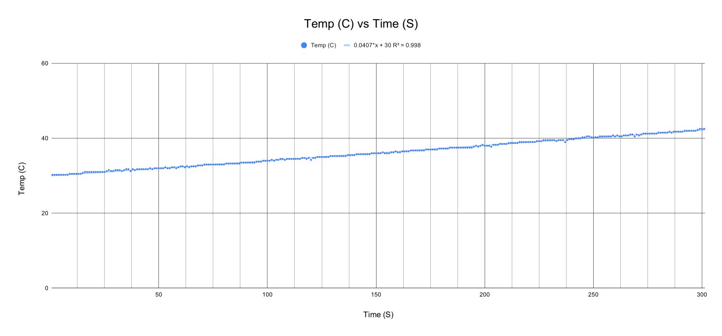
For my first test, I used the high temperature setting on the slow cooker as this allowed the temperature of the bowl to reach over 150 ℃. The first test results were not that exciting. As shown on this chart, the heating profile achieved with the PCB inside the bowl was nice and linear but the rise in temperature was way too slow (0.04 degrees per second).
My first challenge was to determine how I could improve things just using the slow cooker. Then it dawned on me. Who needs the bowl anyway as the heating comes through the aluminium shell. So, I removed the ceramic bowl and I placed the PCB inside the shell with the lid balanced on top (not quite a snug fit).

This provided a much much better temperature gradient (0.16 degree per second) but it still took about 10 to 15 minutes to reach 150 degrees centigrade with the lid on.

It was time to reflect on the science behind this.
The Specific Heat Capacity of a Slow Cooker
The previous Project14 contest (Prove Science!) helped me rethink this engineering challenge. I had already narrowed my focus to the one and only parameter I needed to control, namely temperature, forgetting that if I looked at the system as a whole, which includes energy input and how this impacts the output, namely temperature, then I would get a better handle on the mechanics or science involved to control the system and create an optimum temperature profile.
I now needed to brush up on my science and look at Heat Capacity (which is defined as the amount of heat required to change its temperature by one degree) as well as Specific Heat Capacity which relates to the material properties of the substance being heated as is defined as the amount of heat required to change the temperature of a mass unit of a substance by one degree (source: Engineering Toolbox).
The formula used for Specific Heat Capacity is: c= ΔQ /(m×ΔT) where: c is specific heat capacity; ΔQ is the amount of heat change; m is material mass; ΔT is the change in temperature.
Using online sources, I found that the Specific Heat for Aluminium is around 0.890 J / (g K) and for Ceramic its around 0.85 J / (g K).
As material mass is involved, I put the bowl on the scales and it measured 2.184kg. I had to make estimates for the aluminium shell as I had made some mods before thinking to measure it's mass. I reckon that the shell also weighed about 1.25kg. So combined we could for simplicity assume 3.434kg. We'll see how good are these estimations through our calculations.

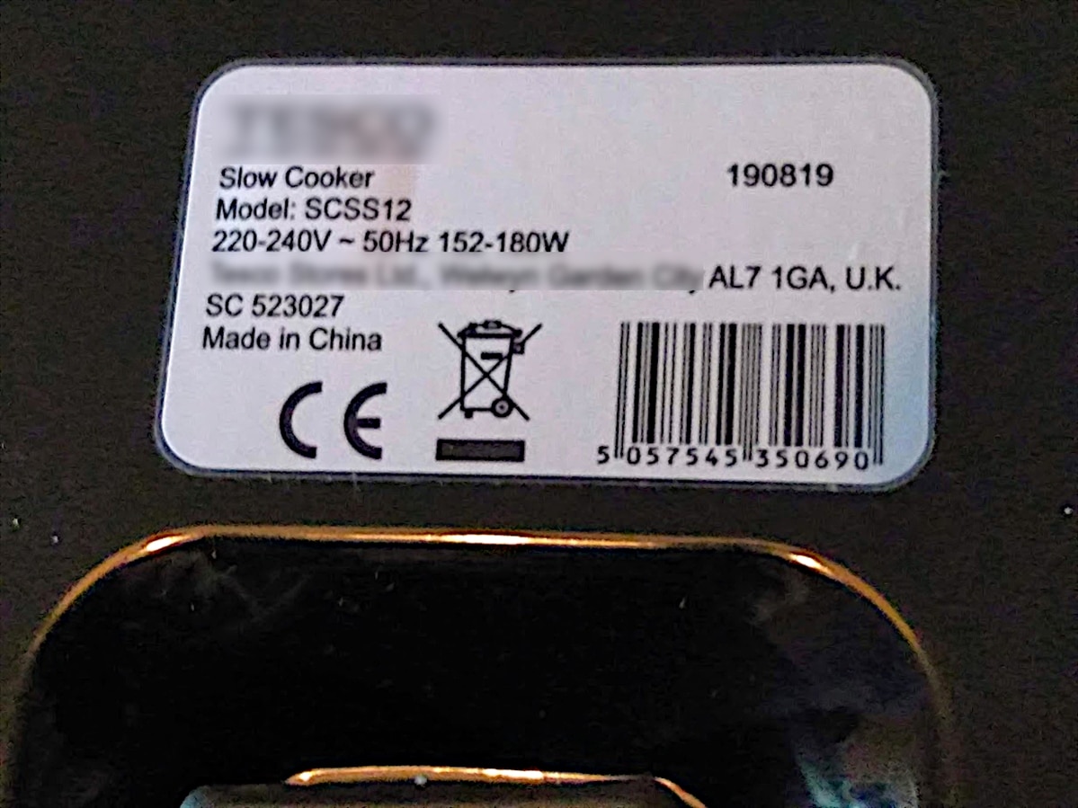
The power rating was found on the underside of the slow cooker:
Let's first look at heating just the aluminium shell + PCB.

Here we calculate that we needed 178W of energy to heat the aluminium shell. Seems plausible considering that the shell is so thin. The chart shows a slight curve that hints at heat losses.
Let's move to the bowl + shell + PCB and use out 178W of power to see what this tells us:
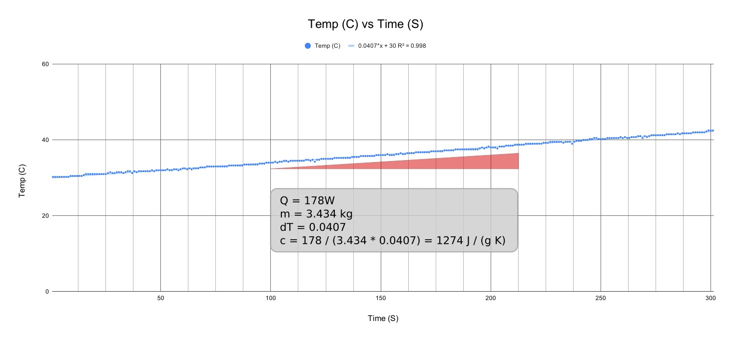
So here it's telling me that the combined Specific Heat Capacity for bowl + shell is 1274 J / (kg K). This is much higher than I was expecting. So there are a few unknown factors have have caused my basic calculations to deviate from the expected ranges. Maybe others have a view as to why. Maybe the bowl is not ceramic but some other material. Maybe the aluminium shell has a different specific heat value too. Maybe the AC voltage fluctuated between the two tests (they were not done on the same day or same time of day) which means that the power value changed. Who knows.
Anyhow, these calculations have now highlighted a new parameter to consider, namely mass of the object being heated. Other considerations would be heat transfers to other objects such as from the inner shell to the outer shell for example. Then there is general thermal loss (I was taking temperature from the top side of the PCB, for example.

One thing this paper exercise did was get me thinking about isolating the inner shell from the outer shell and including some form of insulation between the two layers.
Then I had to consider increasing the energy transfer needed (I needed more power) to increase the temperature gradient.
Introducing another heat source
The first thing I considered was that cheap fan heater I had purchased awhile back. I had posted a question on Element14 website about remote heat control and received some fantastic feedback.
So I hacked together a test apparatus:

Well the test results were very disappointing. The temperature gradient was not great at all and pretty erratic. Clearly temperature control was kicking in. To solve my temperature fluctuation problem, I would have to remove the mechanical type thermostat control mechanism.

Reflecting on options I remembered the drill - keep it simple stupid (kiss). This is especially true when it comes to developing a control system - as another Element14 member has already demonstrated such skill with his Current Control with 1 transistor project.
It was back to the drawing board.
It just so happened that I was rooting around in the shed and I spotted an old flood light lying there (only cost me around $15 at the time). It was one of those that used a 400W halogen R7 type light bulb.

I seemed to recall that these halogen light bulbs were really good a giving off loads of heat, as the exterior casing got very hot. Doing some prelim online research confirmed that these type of light bulbs reach some impressive high temperatures the higher the wattage.
To ensure I got max heat with my 400W flood light, I removed the glass covering and I then balanced the flood light with some wood on top of the slow cooker and turned the light on (cooker remained switched off) and took some temperature measurements.

The results were really encouraging.
I am no PCB reflow expert so I am not sure what the implications are for the initial high temperature gradient (below 65 degree the temperature rise was about 5 degrees per second) but this eventually settled to a steady 1 degree per second rise all the way up to 150 degree, which is pretty darn good, in my opinion.
The problem now was that once I turned off the spotlight, the temperature plummeted as there was no means for heat retention. So definitely some form of active heating control and maybe passive heating insulation will be needed for the soak phase.
I decided to focus on the latter (improved insulation) first to see if I could make things more efficient. I also decided to order in some 230 W R7 Halogen bulbs to see if I could get away with less power.
More on this in the next blog.
Top Comments
-

shabaz
-
Cancel
-
Vote Up
+2
Vote Down
-
-
Sign in to reply
-
More
-
Cancel
-

BigG
in reply to shabaz
-
Cancel
-
Vote Up
+2
Vote Down
-
-
Sign in to reply
-
More
-
Cancel
-

shabaz
in reply to BigG
-
Cancel
-
Vote Up
+3
Vote Down
-
-
Sign in to reply
-
More
-
Cancel
-

genebren
in reply to BigG
-
Cancel
-
Vote Up
+3
Vote Down
-
-
Sign in to reply
-
More
-
Cancel
-

BigG
in reply to shabaz
-
Cancel
-
Vote Up
+2
Vote Down
-
-
Sign in to reply
-
More
-
Cancel
-

BigG
in reply to genebren
-
Cancel
-
Vote Up
+2
Vote Down
-
-
Sign in to reply
-
More
-
Cancel
Comment-

BigG
in reply to genebren
-
Cancel
-
Vote Up
+2
Vote Down
-
-
Sign in to reply
-
More
-
Cancel
Children