


Hello,
Let me introduce the sequel of Traffic Light Controller "from the clouds" v0.1 .
Idea
One of my coworkers asked me to make starting lights for a slot car race track, which is he going to give his boys for birthdays.

Being a MotoGP fan, I started the research, what is the procedure to start the race. There is a difference between F1 rules and MotoGP rules and from what I have read, each has their own sequence. (For simplification, I will skip the preparation time etc, as there is no need to follow a 45 minute procedure for the kids to race  .)
.)
F1 uses 5 red lights that are blank at first. Then, are lit one by one to the point where all 5 are on. Then there is a random delay and all the lights go out. This is the moment to start the race.
MotoGP start is a bit simpler. Again, all lights are blank at first. Then all the red lights are turned on for a random period between 2 to 5 seconds and the race is started as all the lights go out.
Requirements
My goal was to make the lights with the following requirements:
5 red LEDs and a start button is a must. Pushing the start button starts the sequence of a race start (a small delay is needed to have enough time to grab the controller if the driver happens to be a race director at the same time).
Possibility to switch the race procedure from F1 style to MotoGP style.
Random or at least pseudorandom delay for the lights to go out.

Ingredients
- MPLAB Xpress Evaluation board
- LEDs - I chose diffused, not too bright (not to make the kids blind after looking directly into the LED) that light sufficiently at cca 3 mA.
- 5x red LED
- 5x 470 Ohm resistor for each LED (or more, as noted above)
- some wires
- Optionally a battery holder (4x AA / AAA batteries), a single-pole, single-throw switch (SPST), a button, perfboard...
- MPLAB Xpress Cloud-based IDE - no installation needed (Microchip login needed only to save files), JRE for MPLAB Xpress Code Configurator
Hardware
I wrote about the Xpress Evaluation board in my previous blog, so I will just provide a link to the schematics of the board.
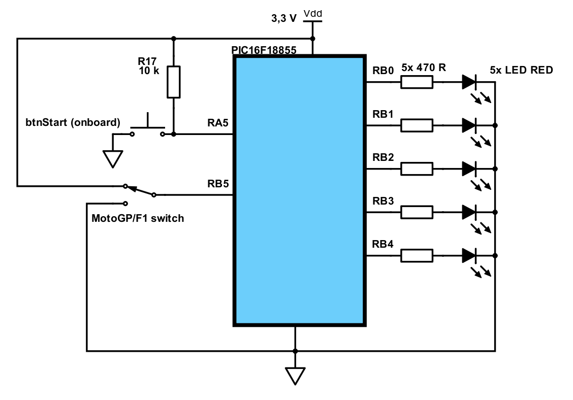
As mentioned in requirements, 5 red LEDs, one switch and a push button is required to be connected to the PIC. Oscillator was selected internal low frequency, running at 31 kHz. Here is a simplified schematics with just the external parts connected to the board (one exception is button connected to RA5 and resistor R17, I used them to minimize the number of external components needed).
Software
Development environment
If you want to know more about the MPLAB Xpress Cloud-based IDE, please see my previous blog with my notes on the overall experience, or try it yourself: MPLAB Xpress Cloud-based IDE
After using it for a few more hours, I have to say that this is probably the last project developed in a cloud-based environment. Nothing can compare to the speed and convenience of using a standalone IDE (or just an editor).
Program
Now comes the fun part. Traffic Light Controller "from the clouds" v0.1 used a Moore finite-state machine model. The same model is used in this build, but there are now two inputs that need to be considered - an F1 / MotoGP start style switch and a button that initiates the starting sequence. What needs to be changed?
The struct that holds all the information for state machine doesn't contain only one nextState variable, but an array of four. Why four? There are two new inputs, each can have two states, that gives four states in total.
Here is how it works. A switch logic state on RB5 is read and a button logic state on RA5 is read. Both bits are stored in the inputSwitches varible in the following way: 0b000000[F1(=1)/MotoGP switch(=0)]|[start button state(1=idle,0=button pressed)].
For each state, all four possible next states are defined, because the input can change anytime. If the input is not important than all four next states can be the same (of unrelated to the meaning of the switch and/or the button). For example all transitions between S_LIGHT1 and S_LIGHT5 are performed this way.
The program works this way:
After a power up, nothing is performed for one second. Then one LED (the middle one) is lit for 300 ms just to show that the power is on and the circuit is ready to take orders. The program is now waiting for a start button to be pushed. That is what initiates the starting sequence. After the start button is pushed, nothing happens for 5 seconds. As described above, this is just a small delay for the player who starts the race to grab the controller and get ready. After the five seconds delay a decision is made, based on the state of the F1/MotoGP mode switch. If set to MotoGP, all 5 LEDs are turned. If the switch was set for an F1 mode, the LEDs are lit gradually up to all five. The rest of the process is the same. A pseudo-random delay is made (using an independently counting Timer0, which 5 LSBs were captured when entering the "5 LEDs on state"). There is a base of 2 seconds and additional 0x - 31x (5 bits from Timer0) 100 ms are added. After that period, all LEDs go out and the state gets back to the "waiting for a push of the start button".
To get the whole picture, here is a diagram of the state machine with all possible transitions:

And here comes the source code:
// Starting Lights v0.1
// David Koudela


#include "mcc_generated_files/mcc.h"


// state numbers
#define S_POWER_ON 0
#define S_ACKNOWLEDGE_POWER_ON 1
#define S_WAIT_FOR_START 2
#define S_PRE_START 3
#define S_LIGHT1 4
#define S_LIGHT2 5
#define S_LIGHT3 6
#define S_LIGHT4 7
#define S_LIGHT5 8


// state output values
// LEDs connected to PORTB4:0
#define OUT_NO_LIGHT 0b00000000 // all LEDs off
#define OUT_ACKNOWLEDGE 0b00000100 // one middle LED on
#define OUT_LIGHT1 0b00010000 // 1 LED in sequence is on
#define OUT_LIGHT2 0b00011000 // 2 LEDs in sequence are on
#define OUT_LIGHT3 0b00011100 // 3 LEDs in sequence are on
#define OUT_LIGHT4 0b00011110 // 4 LEDs in sequence are on
#define OUT_LIGHT5 0b00011111 // 5 LEDs in sequence are on


// period definitions in multiplies of 100 ms
#define DELAY_POWER_ON 10 // 1 second
#define DELAY_ACKNOWLEDGE 3 // 300 ms
#define DELAY_PRE_START 50 // 5 seconds
#define DELAY_LIGHT_ON 10 // 1 second
#define DELAY_NONE 0 // 0 ms


// struct for holding the configuration of a state
typedef const struct {
    unsigned char LightsOutput; // output of the current state - saying which LED(s) should be lit
    unsigned char delay; // delay in multiplies of 100 ms; how long a state lasts
    unsigned char nextState[4]; // array of possible next states, will depend on two input values of a switch and a button [F1(=1)/MotoGP switch(=0)]|[start button state(1=idle,0=button pressed)]
} SLState;


// definition of the state machine for the starting lights
SLState StartingLightFSM[9] = {
    {OUT_NO_LIGHT, DELAY_POWER_ON, {S_ACKNOWLEDGE_POWER_ON, S_ACKNOWLEDGE_POWER_ON, S_ACKNOWLEDGE_POWER_ON, S_ACKNOWLEDGE_POWER_ON} }, // S_POWER_ON
    {OUT_ACKNOWLEDGE, DELAY_ACKNOWLEDGE, {S_WAIT_FOR_START, S_WAIT_FOR_START, S_WAIT_FOR_START, S_WAIT_FOR_START} }, // S_ACKNOWLEDGE_POWER_ON
    {OUT_NO_LIGHT, DELAY_NONE, {S_WAIT_FOR_START, S_PRE_START, S_WAIT_FOR_START, S_PRE_START} }, // S_WAIT_FOR_START
    {OUT_NO_LIGHT, DELAY_PRE_START, {S_LIGHT5, S_LIGHT5, S_LIGHT1, S_LIGHT1} }, // S_PRE_START
    {OUT_LIGHT1, DELAY_LIGHT_ON, {S_LIGHT2, S_LIGHT2, S_LIGHT2, S_LIGHT2} }, // S_LIGHT1
    {OUT_LIGHT2, DELAY_LIGHT_ON, {S_LIGHT3, S_LIGHT3, S_LIGHT3, S_LIGHT3} }, // S_LIGHT2
    {OUT_LIGHT3, DELAY_LIGHT_ON, {S_LIGHT4, S_LIGHT4, S_LIGHT4, S_LIGHT4} }, // S_LIGHT3
    {OUT_LIGHT4, DELAY_LIGHT_ON, {S_LIGHT5, S_LIGHT5, S_LIGHT5, S_LIGHT5} }, // S_LIGHT4
    {OUT_LIGHT5, 30, {S_WAIT_FOR_START, S_WAIT_FOR_START, S_WAIT_FOR_START, S_WAIT_FOR_START} } // S_LIGHT5
};


// variable to hold the current state
unsigned char currentState;
// variable to hold the state of two input values - a switch and a button
unsigned char inputSwitches;
// variable to create a longer delay in multiplies of 100 ms
unsigned char delay100ms;


/*
                         Main application
 */
void main(void)
{
    // initialize the device - pins, an oscillator and Timer0
    SYSTEM_Initialize();

    // set the state in wich the FSM starts
    currentState = S_POWER_ON;


    // endless loop
    while (1)
    {
        // output a LED pattern of a current state to PORTB latch
        LATB = StartingLightFSM[currentState].LightsOutput;

        // assign the delay value (in multiplies of 100 ms) from FSM definition to the delay variable
        // the only exception is the final state with 5 LEDs on, where the delay is random, 2 - 5 seconds long
        // pseudorandom element is introduced by reading 5 LSBs of Timer0 (running at 31 kHz)
        if (currentState == S_LIGHT5) {
            delay100ms = TMR0L;
            delay100ms &= 0b00011111;
            delay100ms += 20u;
        } else {
            delay100ms = StartingLightFSM[currentState].delay;
        }

        // delay for a desired number of 100 ms
        // embedded delay library can have problem with generating longer delays at higher frequencies
        for (delay100ms; delay100ms > 0; delay100ms-- ) {
            __delay_ms(100u);
        }


        // the following code reads state of the F1 / MotoGP start style switch and state of the start button
        // only two LSBs of inputSwitches variable are used:
        // 0b000000[F1(=1)/MotoGP switch(=0)]|[start button state(1=idle,0=button pressed)]

        // read the F1 / MotoGP switch value, place the value in bit 1 of inputSwitches
        // and mask all other bits so they are not affected
        if (IO_SW_F1_MGP_GetValue()) { inputSwitches |= 0b00000010; }
            else { inputSwitches &= 0b11111101; }


        // read the start button value, place the value in bit 0 of inputSwitches
        // and mask all other bits so they are not affected
        if (IO_BTN_START_GetValue()) { inputSwitches &= 0b11111110; }
            else { inputSwitches |= 0b00000001; }

        // determine the next state from the current state and combination of input (switch and
        currentState = StartingLightFSM[currentState].nextState[inputSwitches];

    }
}
/**
 End of File
*/
Video
Here is a video proof of work. We don't have slot cars race track at home, so I tested the lights with model cars. Both videos start with plugging in the USB to a computer (off the camera).
Please excuse that it is not a finished product yet.
F1 style start:
PS: I had a model of an F1 car, but it drove off the table during test run to the area I can't access without moving a wardrobe and the table
MotoGP style start:
What to do next
Some ideas are:
1) Make this a finished product, place the LEDs on some pillar etc.
2) Embed a siren for signaling periods before starting the countdown (for real races, there are sirens for the crew to get out of the racing track, 3 and one minutes before the warm-up lap etc.). Only if this doesn't make the parents crazy, of course
3) Add sensors for jump-start detection: probably optical for each lane. After adding these, some new possibilities open, for example a lap timer.
What do you think? Is there anything that you would do differently?
Thank you for reading and watching.
David
Top Comments