element14 Community
element14 Community
    Register Log In
  • Site
  • Search
  • Log In Register
  • About Us
  • Community Hub
    Community Hub
    • What's New on element14
    • Feedback and Support
    • Benefits of Membership
    • Personal Blogs
    • Members Area
    • Achievement Levels
  • Learn
    Learn
    • Ask an Expert
    • eBooks
    • element14 presents
    • Learning Center
    • Tech Spotlight
    • STEM Academy
    • Webinars, Training and Events
    • Learning Groups
  • Technologies
    Technologies
    • 3D Printing
    • FPGA
    • Industrial Automation
    • Internet of Things
    • Power & Energy
    • Sensors
    • Technology Groups
  • Challenges & Projects
    Challenges & Projects
    • Design Challenges
    • element14 presents Projects
    • Project14
    • Arduino Projects
    • Raspberry Pi Projects
    • Project Groups
  • Products
    Products
    • Arduino
    • Avnet Boards Community
    • Dev Tools
    • Manufacturers
    • Multicomp Pro
    • Product Groups
    • Raspberry Pi
    • RoadTests & Reviews
  • Store
    Store
    • Visit Your Store
    • Choose another store...
      • Europe
      •  Austria (German)
      •  Belgium (Dutch, French)
      •  Bulgaria (Bulgarian)
      •  Czech Republic (Czech)
      •  Denmark (Danish)
      •  Estonia (Estonian)
      •  Finland (Finnish)
      •  France (French)
      •  Germany (German)
      •  Hungary (Hungarian)
      •  Ireland
      •  Israel
      •  Italy (Italian)
      •  Latvia (Latvian)
      •  
      •  Lithuania (Lithuanian)
      •  Netherlands (Dutch)
      •  Norway (Norwegian)
      •  Poland (Polish)
      •  Portugal (Portuguese)
      •  Romania (Romanian)
      •  Russia (Russian)
      •  Slovakia (Slovak)
      •  Slovenia (Slovenian)
      •  Spain (Spanish)
      •  Sweden (Swedish)
      •  Switzerland(German, French)
      •  Turkey (Turkish)
      •  United Kingdom
      • Asia Pacific
      •  Australia
      •  China
      •  Hong Kong
      •  India
      •  Korea (Korean)
      •  Malaysia
      •  New Zealand
      •  Philippines
      •  Singapore
      •  Taiwan
      •  Thailand (Thai)
      • Americas
      •  Brazil (Portuguese)
      •  Canada
      •  Mexico (Spanish)
      •  United States
      Can't find the country/region you're looking for? Visit our export site or find a local distributor.
  • Translate
  • Profile
  • Settings
Crazy Arduino Automations
  • Challenges & Projects
  • Project14
  • Crazy Arduino Automations
  • More
  • Cancel
Crazy Arduino Automations
Crazy Arduino Automations Blog Raising the Bridge...Automation with Arduino: Failure reconciliation
  • Blog
  • Forum
  • Documents
  • Files
  • Members
  • Mentions
  • Sub-Groups
  • Tags
  • More
  • Cancel
  • New
Join Crazy Arduino Automations to participate - click to join for free!
  • Share
  • More
  • Cancel
Group Actions
  • Group RSS
  • More
  • Cancel
Engagement
  • Author Author: colporteur
  • Date Created: 20 Apr 2023 8:29 PM Date Created
  • Views 4403 views
  • Likes 10 likes
  • Comments 16 comments
  • crazyarduinoautomationch
Related
Recommended

Raising the Bridge...Automation with Arduino: Failure reconciliation

colporteur
colporteur
20 Apr 2023

I have made unserviceable two L293N and one L298N motor driver modules doing something but I don't know what. I would like to know what I did, so I can prevent it from happening in the future. Can anyone share their experience or knowledge to help me isolate the cause of these failures?

L293NL298N

As part of the Automation Design Challenge I am developing a solution to raise the bridge on a model railroad layout. 

image

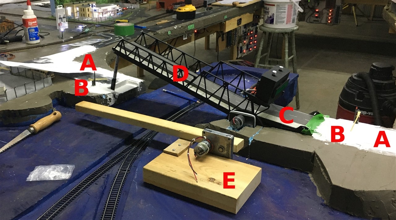
Model railroaders have been busy working on building the bridge. A magnet raised and lowered using a servo motor are located under the roadbed at points A. The barrier gates that are raised and lowered via servo are at points B. A ramp at point C is raised and lowered to make room for the bridge point D, to move is also controlled by a servo. The bridge has a separate motor to raise and lower it.

While the model railroaders are putting the finishing touches on the bridge installation, automation development continues. I built a bridge simulator point E using the same model of motor that is used for the bridge movement. My goal was to use the simulator to resurrect Arduino code that will manage the raising and lowering of the bridge. 

In the past I have smoked electronics and had to tear apart the layout to make repairs. The simulator will hopefully eliminate that step:)

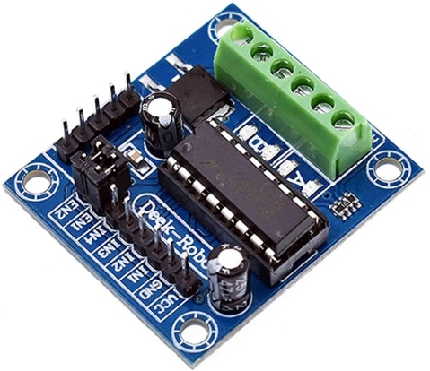
The test unit has the motor moving an arm, controlled by a Nano and switches (not shown in the picture). The Nano uses an L293N or L298N to drive the motor. I did about three hours of testing with an L293N module raising and lowering the arm before it didn't work anymore. I can’t recall doing anything that would result in the failure. I replaced the driver module and continued to test but once again I did something to cause it not to work.

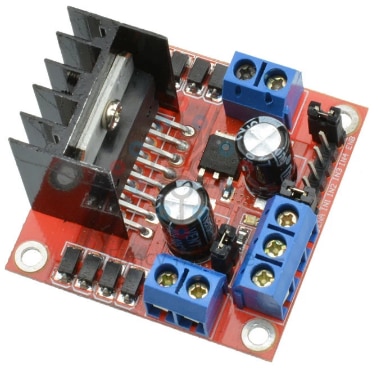
I took the assembly home and continued to test (while watching the playoff hockey games) and discovered the failed modules are outputting a little less than a half of the motor supply voltage of 12V. I then tried a spare L298N module I had and performed some tests.

It initially worked. 12V was being outputted to the motor. At one point I prevented the arm from rising. I also noticed the module LED’s come on when I pushed the arm back down. The L298N didn’t work after that. Did the action of preventing the arm from rising or pushing it down, smoked the chips. I’m just not sure?

My speculation is either preventing the motor to raise the arm or pushing the arm down might have caused a back emf that damaged the driver chips. There is a possibility that this action may happen when the bridge goes into production. As you can see from the picture the bridge is exposed to operators.

I have worked with these driver modules in the past to control motor speed with no issue. In those scenarios, I wasn’t impeding the motor movement. I made some amateur mistakes (shite happens) like shorting outputs but the chips still worked.

I recall before damaging the first two L293N modules I did impede the motor by stopping the arm but no damage was apparent because I was able to continue testing. Maybe at low motor speed settings impeding the arm is not a problem but at max settings the chip is damaged. I’m not sure?

If anyone has any insights, suggestions or condolences please pass them along. I have no more spares at the moment so I have to park the project until a delivery truck arrives.

  • Sign in to reply

Top Comments

  • colporteur
    colporteur over 2 years ago in reply to Jan Cumps +1
    Appreciate the response. You challenge me J, I like that. I found this definition of dead-band, hope I am on the same page as you. There is no mention of it in the data sheets that I found. In Half-Bridge…
  • colporteur
    colporteur over 2 years ago +1
    I had put further troubleshooting of the issue with the L293D until I had some spares. I received L293D driver chips this week. My thought was to replace the chip in the problem modules to determine if…
  • scottiebabe
    scottiebabe over 2 years ago in reply to colporteur

    image

    • Cancel
    • Vote Up 0 Vote Down
    • Sign in to reply
    • More
    • Cancel
  • robogary
    robogary over 2 years ago

    The photo is really helpful. The stalled motor current is likely more current than the h bridge can handle long term. If the pwm output motor rms voltage  is lower , the rms stall current is lower. You can get an idea of the motor resistance by checking the dc motor leads with an ohmmeter. Stall current is the max volts applied to the motor, divided by that resistance. You could try resistors in series with the motor to limit stall current to 2 amps or less. The motors will automatically slow down as load increases, giving them a speed droop feature 

    • Cancel
    • Vote Up 0 Vote Down
    • Sign in to reply
    • More
    • Cancel
  • colporteur
    colporteur over 2 years ago

    I had put further troubleshooting of the issue with the L293D until I had some spares. I received L293D driver chips this week. My thought was to replace the chip in the problem modules to determine if it was the cause of the failure. Then I would repeat some tests to see what lets the smoke out of the chip.

    image

    Changing the integrated circuit

    DIDN'T RESOLVE THE ISSUE!

    Crap! What did I overlook in my testing? Back to the meter. I struggled with the specification sheet. Something wasn't right.

    image

    image

    I confess I am not the sharpest tool in the shed when it comes to electronic gardening. My electronics career forked into System Administration in 1996 so some of the stuff in memory is rusty. I had used the L293D modules in two other projects with success. The failure this time came as a surprise. I take it as a failure on my part when I let the smoke out of components when I am building something,  So I work real hard to keep the smoke in.

    My problem with the driver chip was the two supplies VCC1 & VCC2. I hate the VCC references in the spec sheet. One supply powers the chip and the other is used by the chip to power the load. On the module PCB there are inputs, VCC is 5V for the chip and Vin is the motor supply. You can see this on the module image on the left.

    A meter reading of the modules Pin 16 VCC1 is 12V. Meter meting of Pin 8 VCC2 is 5V. Wait a minute the values are reversed. After much consternation and nashing of teeth I discovered I must have put the chip in backwards???

    image

    The screen shot on the left is the orientation of the L293D chip from a picture on the website and the two modules on the right are what is installed. Note the position of the red circles that show the chip orientation key.

    Putting the chip in backwards is something that can happen but here is the kicker, I never removed the chips. They were installed backwards when I received the modules.. The two modules on the right image are installed and working. The three L293D modules I thought I had damaged had the L293D chip installed backwards also. That is five modules delivered from the supplier with the chip installed backwards.

    With the chip in the correct orientation the voltages at the power pin begin to make sense %v is where you would expect it. With the chip in the correct orientation the modules work. No parts replacement required.

    I did discover measuring the voltages at the motor points with no load appears to work but slightly lower. With a motor load attached the voltage sinks. I can only speculate the two modules that are working is because the load is not that great.

    My actions didn't cause the failures. I now have five L293D spare integrated circuits.

    • Cancel
    • Vote Up +1 Vote Down
    • Sign in to reply
    • More
    • Cancel
  • colporteur
    colporteur over 2 years ago

    I have order some replacement components for the L293N & L298N.

    If you are squeamish about seeing devices destroyed than I recommend you drop following this post.

    In the interest of learning, I plan to sacrifice at least one of each of the component in a recreation of what I believe caused failures.

    • Cancel
    • Vote Up 0 Vote Down
    • Sign in to reply
    • More
    • Cancel
  • robogary
    robogary over 2 years ago

    wow- I've had pretty good luck with these bridges, it could be luck or the way I use them. 

    #1 - I usually fuse upstream from the H bridge in case of accidental short (short term instantaneous current) , and long term current (overload current).

    It could be the motor current overloads the bridge. 

    #2 - I dont slam the H bridge full FWD, or full REV  with full PWM. First have PWM duty = 0, enable the FWD or REV and increment the PWM duty to 1023 (or is it 255?) in a quarter second or so, or whatever accel/decel you want. To stop, first reduce the PWM duty from the set value to zero, then turn off the FWD or REV bit.  

    I have used these IBT-4 50A bridges in some projects , and they have been running for years. 

    https://www.amazon.com/H-Bridge-High-Power-Single-Channel-Semiconductor-Refrigeration/dp/B07PM76KJG/ref=sr_1_1_sspa?crid=1N78ZSPXO8QN7&keywords=H+bridge&qid=1682129796&sprefix=h+br%2Caps%2C785&sr=8-1-spons&psc=1&smid=A2P6NQ66D5K6F0&spLa=ZW5jcnlwdGVkUXVhbGlmaWVyPUEyMUFCMVA3QVBSN01XJmVuY3J5cHRlZElkPUEwNTEzMDgyMUJQQkVIRFVMR0wwVCZlbmNyeXB0ZWRBZElkPUEwMzA4NDU0M01NSk5QMjRUOE1UUiZ3aWRnZXROYW1lPXNwX2F0ZiZhY3Rpb249Y2xpY2tSZWRpcmVjdCZkb05vdExvZ0NsaWNrPXRydWU=

    • Cancel
    • Vote Up 0 Vote Down
    • Sign in to reply
    • More
    • Cancel
>
element14 Community

element14 is the first online community specifically for engineers. Connect with your peers and get expert answers to your questions.

  • Members
  • Learn
  • Technologies
  • Challenges & Projects
  • Products
  • Store
  • About Us
  • Feedback & Support
  • FAQs
  • Terms of Use
  • Privacy Policy
  • Legal and Copyright Notices
  • Sitemap
  • Cookies

An Avnet Company © 2025 Premier Farnell Limited. All Rights Reserved.

Premier Farnell Ltd, registered in England and Wales (no 00876412), registered office: Farnell House, Forge Lane, Leeds LS12 2NE.

ICP 备案号 10220084.

Follow element14

  • X
  • Facebook
  • linkedin
  • YouTube