element14 Community
element14 Community
    Register Log In
  • Site
  • Search
  • Log In Register
  • About Us
  • Community Hub
    Community Hub
    • What's New on element14
    • Feedback and Support
    • Benefits of Membership
    • Personal Blogs
    • Members Area
    • Achievement Levels
  • Learn
    Learn
    • Ask an Expert
    • eBooks
    • element14 presents
    • Learning Center
    • Tech Spotlight
    • STEM Academy
    • Webinars, Training and Events
    • Learning Groups
  • Technologies
    Technologies
    • 3D Printing
    • FPGA
    • Industrial Automation
    • Internet of Things
    • Power & Energy
    • Sensors
    • Technology Groups
  • Challenges & Projects
    Challenges & Projects
    • Design Challenges
    • element14 presents Projects
    • Project14
    • Arduino Projects
    • Raspberry Pi Projects
    • Project Groups
  • Products
    Products
    • Arduino
    • Avnet Boards Community
    • Dev Tools
    • Manufacturers
    • Multicomp Pro
    • Product Groups
    • Raspberry Pi
    • RoadTests & Reviews
  • Store
    Store
    • Visit Your Store
    • Choose another store...
      • Europe
      •  Austria (German)
      •  Belgium (Dutch, French)
      •  Bulgaria (Bulgarian)
      •  Czech Republic (Czech)
      •  Denmark (Danish)
      •  Estonia (Estonian)
      •  Finland (Finnish)
      •  France (French)
      •  Germany (German)
      •  Hungary (Hungarian)
      •  Ireland
      •  Israel
      •  Italy (Italian)
      •  Latvia (Latvian)
      •  
      •  Lithuania (Lithuanian)
      •  Netherlands (Dutch)
      •  Norway (Norwegian)
      •  Poland (Polish)
      •  Portugal (Portuguese)
      •  Romania (Romanian)
      •  Russia (Russian)
      •  Slovakia (Slovak)
      •  Slovenia (Slovenian)
      •  Spain (Spanish)
      •  Sweden (Swedish)
      •  Switzerland(German, French)
      •  Turkey (Turkish)
      •  United Kingdom
      • Asia Pacific
      •  Australia
      •  China
      •  Hong Kong
      •  India
      •  Korea (Korean)
      •  Malaysia
      •  New Zealand
      •  Philippines
      •  Singapore
      •  Taiwan
      •  Thailand (Thai)
      • Americas
      •  Brazil (Portuguese)
      •  Canada
      •  Mexico (Spanish)
      •  United States
      Can't find the country/region you're looking for? Visit our export site or find a local distributor.
  • Translate
  • Profile
  • Settings
Crazy Arduino Automations
  • Challenges & Projects
  • Project14
  • Crazy Arduino Automations
  • More
  • Cancel
Crazy Arduino Automations
Crazy Arduino Automations Blog Raising the Bridge...Automation with Arduino: Pin Count
  • Blog
  • Forum
  • Documents
  • Files
  • Members
  • Mentions
  • Sub-Groups
  • Tags
  • More
  • Cancel
  • New
Join Crazy Arduino Automations to participate - click to join for free!
  • Share
  • More
  • Cancel
Group Actions
  • Group RSS
  • More
  • Cancel
Engagement
  • Author Author: colporteur
  • Date Created: 28 Mar 2023 11:22 PM Date Created
  • Views 2493 views
  • Likes 6 likes
  • Comments 21 comments
  • crazyarduinoautomationch
Related
Recommended

Raising the Bridge...Automation with Arduino: Pin Count

colporteur
colporteur
28 Mar 2023

image

The comments posted from my initial blog entry got me to thinking. Did I size this correctly?

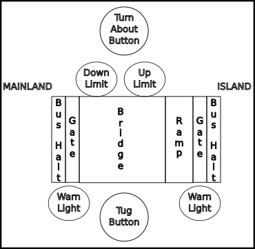
The bridge spans the Mainland to Island. At either end of the bridge is a gate, an area to halt the bus and warning lights flashing when the bridge is closed. In addition to the lights, I've added a warning sound. At one end of the bridge is a ramp that enables the bridge to avoid the road bed as it rises. A trigger to raise the bridge will be the Tug and to lower the bridge the Turn-About. The bridge motor is using a L298 module and the bus halts, gates and ramp are servo motors. All toll I'm counting 14 pins required.

D2 Bridge Up limit
D3~ Ramp Servo
D4 Bridge Down Limit
D5~ Island Gate Servo
D6~ Mainland Gate Servo
D7 Bridge L298 Motor IN2
D8 Bridge L298 Motor IN1
D9~ Bridge L298 Motor EN A
D10~ Island Bus Halt Servo
D11~ Mainland Bus Halt Servo
D12 Warning Sound JQ6500
D13 Tug Sensor
D14 Turn-about Button
D15/A0 Island Warning Light
D16/A1 Mainland Warning Light
  • Sign in to reply
  • beacon_dave
    beacon_dave over 2 years ago in reply to beacon_dave

    You could have an isolated track section that runs under the bridge, which only has power applied when the 'bridge raised' limit switch is triggered. That will help prevent the tug from ramming the bridge when the bridge is in the lowered position.

    • Cancel
    • Vote Up 0 Vote Down
    • Sign in to reply
    • More
    • Cancel
  • beacon_dave
    beacon_dave over 2 years ago in reply to colporteur

    You might need a Mega2560 at this rate for the increased IO.

    For each bus stop location you will likely need a sensor to detect the bus and then an actuator to stop the bus. Although with only one bus you could tie all the stop actuators together onto one output.

    • Cancel
    • Vote Up 0 Vote Down
    • Sign in to reply
    • More
    • Cancel
  • beacon_dave
    beacon_dave over 2 years ago in reply to colporteur

    So how does the 'current plan' prevent the ramp / bridge from raising when there is a bus on it ? The stop servo will only stop the bus if it reaches it after the tug has tripped the sensor. If the bus passes the stop servo just before the tug trips the sensor it will be entering the bridge as it starts to raise.

    The gate at the far end will be closed as well so if the bus makes it across the bridge, it will then likely hit the gate. It will then stop once it reaches the stop servo on the far side of the gate.

    Adding a delay before closing the gate and lifting the bridge will allow the bus to get across but it will still stop at the stop servo on exiting the bridge, so the closing gate could hit the back end of the bus.

    I think that scenario is what additional magnet is for:

    image

    There is a bus stop option as part of the official kit. 

    image

    https://www.faller.de/en/car-system/road-construction-accessories/887/laser-street-bus-stop-set?c=39

    Which uses a diverter motor that changes the wire path from straight ahead into a bus stop siding. So looks like buses fitted with magnets can trigger the diverter when approaching the bus stop whilst other vehicles continue straight on. Bus goes into the siding where it hits a stop servo.

    • Cancel
    • Vote Up 0 Vote Down
    • Sign in to reply
    • More
    • Cancel
  • colporteur
    colporteur over 2 years ago in reply to beacon_dave

    More extensive automation than in the current plan.

    I curious about the magnetic suggestion. I am currently looking for a way to detect the bus as it travels the loop. The goal is to have the bus randomly stop at bus stops.  Maybe a hall effect sensor embedded in the roadway can tell me where the bus is at.

    If you are on the north american side of the pond I could sure use the extra pair of technical hands.

    The kit electronics are expensive. The hobby is not cheap and looking at fancy stuff doesn't make it cheaper:) I enjoy coming up with inexpensive solutions. I have a hall effect sensor in the spares box to give this a try. Keep the ideas coming!

    • Cancel
    • Vote Up 0 Vote Down
    • Sign in to reply
    • More
    • Cancel
  • beacon_dave
    beacon_dave over 2 years ago in reply to beacon_dave

    It looks like the Faller system has the option for an additional magnet.

    image

    As it is offset from centre then this could be used to detect direction of travel on a single track with end loops system and you could then count vehicles on and off the bridge.

    You would need two reed switches at either end of the bridge (time to dig up the road) and some more Arduino inputs.

    With a single gate either end you probably want some traffic lights as well The traffic light indicates for the traffic approaching the bridge to stop, whereas the lowered gates indicate the bridge is clear of traffic and is ready to raise. 

    You can then have an up/down counter driven by the reed switches to track vehicles on the bridge, and only lower the gates if it is at zero. 

    Placement of those reed switches will depend on the design of the roadway as if it is single track then the stop servo needs to only stop vehicles from entering the bridge and not vehicles exiting the bridge. It might be useful to know if there is a vehicle stopped, in which case the reed switches in the road and in the vehicle need to be activated at the same time, but this may depend on the positions of the additional magnet on vehicles of differing lengths.

    Also depends on the number of vehicles in use at any one time as well, although the stop servo suggests that only one vehicle is ever expected to be waiting at the bridge at any one time, otherwise another vehicle would drive into the back of the one waiting.

    • Cancel
    • Vote Up 0 Vote Down
    • Sign in to reply
    • More
    • Cancel
>
element14 Community

element14 is the first online community specifically for engineers. Connect with your peers and get expert answers to your questions.

  • Members
  • Learn
  • Technologies
  • Challenges & Projects
  • Products
  • Store
  • About Us
  • Feedback & Support
  • FAQs
  • Terms of Use
  • Privacy Policy
  • Legal and Copyright Notices
  • Sitemap
  • Cookies

An Avnet Company © 2025 Premier Farnell Limited. All Rights Reserved.

Premier Farnell Ltd, registered in England and Wales (no 00876412), registered office: Farnell House, Forge Lane, Leeds LS12 2NE.

ICP 备案号 10220084.

Follow element14

  • X
  • Facebook
  • linkedin
  • YouTube