

One of the key reasons I wanted to build a SAR ADC is its heart is a digital-to-analog converter (DAC). So it is a two-for-one project. As a quick summary, a SAR ADC uses a DAC to generate analog voltages that get compared to the input voltage. Using a binary search, it is possible to find a digital code that represents the input.
Quite a bit has changed from the first part. In the last post, I was thinking about a shift register and how to control the LEDs. Ultimately, I with the shift register route and added a buffer chip for individual LED control. I've also gotten the boards back, built, and tested them. Things are moving forward!
Bald Bit Boards
The first step in my VADC project was to design an R-2R ladder. My goal was to create individual "bit boards" with a resistor, relay, and LEDs. The resistors are obvious because they build the R-2R ladder. The relay and LEDs are entirely for visualization purposes. I decided the PCB should light up around the relay whenever that particular bit is active. Each bit board contains six LEDs and one relay. The relay determines if the resistor is in the ladder or not. The LEDs are these reverse mount LEDs from Wurthreverse mount LEDs from Wurth. (More on being reverse mount below.)

To drive the relay plus six LEDs, I decided to add a 74HCT595 74HCT595 shift register to each board. Using a shift register means I can daisy-chain multiple boards together. Initially, I built four boards for a 4-bit DAC. But in theory, I should easily be able to extend to 8-bits+. (Well, I would have already built them if the rest of my LEDs were not back-ordered. grr.)
Instead of using discrete transistors to drive the LEDs, I decided to add a 74HC245 74HC245 buffer. It can provide up to 70 mA total on its outputs, which should be sufficient for this project. The LEDs have a fairly high forward voltage, so a 330 ohm limiting resistor means I'm drawing 9 mA each. So the LEDs draw 54 mA total (if they are all on). The only real consideration is the relay's coil.

For the relay, I decided to include a P-Channel MOSFET configured as a high-side switch. That way, the `595 output can directly drive the transistor. For flyback protection, I added a 1n4001. Although, it is probably overkill for this relay. I'm using these Multicomp Pro Signal RelaysMulticomp Pro Signal Relays. And they are tiny! They are so small; I was initially concerned they would not click loud enough! (Spoiler Alert: No worries, they do.)
Why 4-layer?
If you look at the vADC KiCad design files, you'll probably notice the PCB is 4-layers. Why?
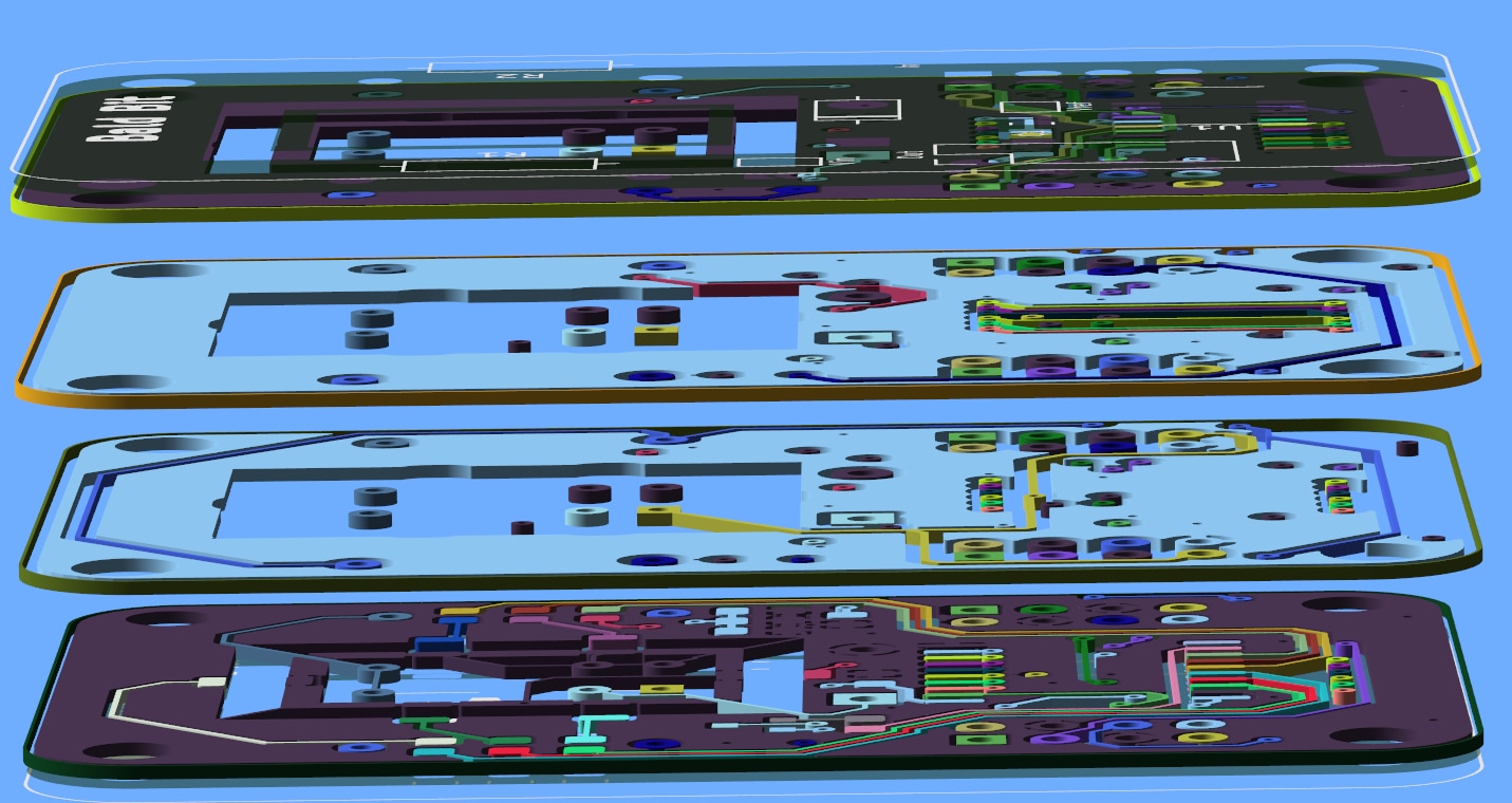
Well, first, my go-to PCB supplier is OSH Park, especially if the project is below 100 mm2. And second, I am using reverse mount LEDs to create a glowing ring around the relay. (or that was the plan.) OSH Park's FR4 formulation is different from their 2-layer, and it is more fluorescent. While the signal integrity of this design didn't need four layers, the cool visualization integrity did!
Soldering
When soldering a board with more than a few components, you can almost always expect at least one mistake. When soldering multiple boards with multiple components, it is a certainty. Shockingly, there were almost no mistakes in assembly the first four boards. At least, no circuit mistakes. I'm not great with hot air, so I had some intermittent behavior with one LED. That was fixed by resoldering the `595 with my normal iron.
That said, I did accidentally touch the exposed ground plane with my soldering iron. So, some solder ended up on the gold finish. I left that area exposed on both sides of the board to make clipping on a scope easier. I'm really hoping I can sacrifice that board as extra because I want the gold strip to stay "clean."
Code
void send_data_to_bits(uint32_t data_out) {
    // X R X X  X X X 1  X R X X  X X X 1   X R X X  X X X 1   X R X X  X X X 1
    digitalWrite(latch_595, HIGH);
      shiftOut(data_595, clock_595, MSBFIRST, (data_out >> 24));  // bit 4
     shiftOut(data_595, clock_595, MSBFIRST, (data_out >> 16));  // bit 3
     shiftOut(data_595, clock_595, MSBFIRST, (data_out >> 8));    // bit 2
     shiftOut(data_595, clock_595, MSBFIRST, (data_out));        // bit 0
    digitalWrite(latch_595, LOW);
}
Interfacing the daisy-chained bit boards is straightforward. The only hiccup I ran into is that Arduino's shfitOut() only accepts 8-bits or a byte. Since each bit board has its own `595, each board has 8-bits of data to handle. So I had to do some barrel shifting to get the expected outputs. Even with 32-bits of data, I found I could update the LEDs once every 25 milliseconds. From a visualization perspective, that is probably too fast, but it is good to know I have plenty of headroom to flash the LEDs.
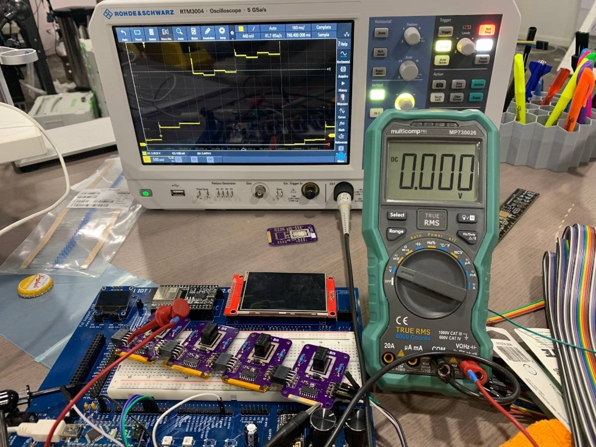
Scope Capture
In the video above, you can see that the multimeter measures a different voltage as the bit values change. Astute viewers might notice that the voltage starts close to 5 volts and ends near 0 volts. From a DAC perspective, this range is irrelevant. However, for the visualization, I think it makes more sense for the voltage to go from 0 volts to 5 volts as the binary codes go from 0x0 to 0xF. So, later, I inverted the relays. This change means while the relay is lit up, it is actually off. In retrospect, I should have swapped Vref and GND on the relay contacts.
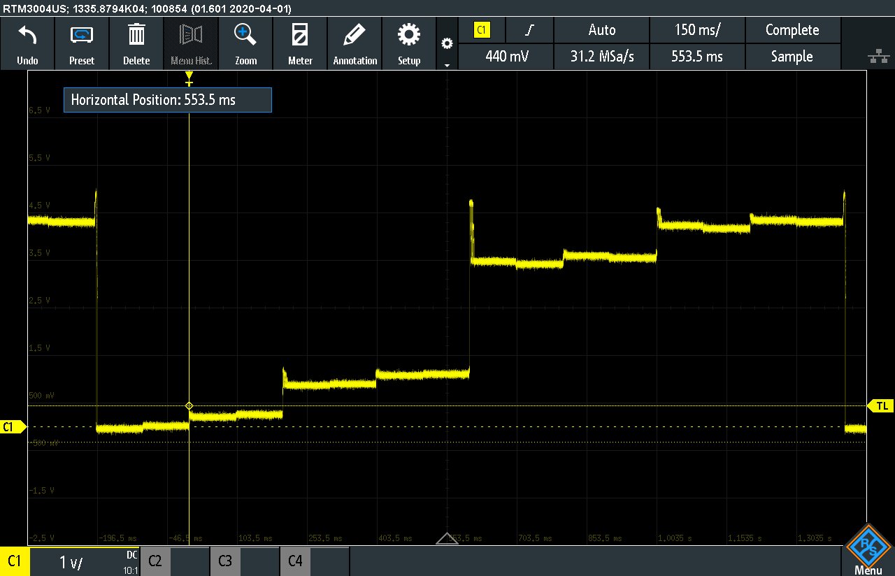
After making that code change, I captured the codes on my scope. And to my surprise, there is a huge gap between 0x7 and 0x8. Upon further inspection of the Bit Boards, I put the "R" and "2R" values in the wrong places! So, the ladder is just output nonsense. The positive news is that different binary values result in different outputs.
Next Steps
Since I have to order some more parts to build another 4-bits, I decided to splurge on some 0.1% resistors to match my R-2R values better. When I get those, I'll fix these four initial bits. In the meantime, I've already built up a functional sample-and-hold amplifier AND a comparator circuit. But, those are a topic for another post.
Super Quick Update
The DAC not going to 0V when the binary codes are zero was bothering a friend of mine. Which after he asked the question, it started to bother me too. After thinking about it, I had an idea why. "VIN" on the least significant bit is supposed to be connected to ground. In the video at the top of the post, it is left open. After making that change, now the DAC goes from 0.00 volts to about 4.2 volts. (but the codes are not linear or in order because the resistor values are still wrong.)
Top Comments