

Any physical quantity in our world has to be converted to a voltage to be measured in electronics. Even if you have a sensor that outputs a digital bus like SPI or I2C, inside of that sensor is an ADC. There are many types, with Flash, SAR, and Sigma-Delta being very common. Like all things in engineering, there are advantages (and disadvantages) to each analog-to-digital converter type.
Since I did not have a project in mind for converting a physical quantity, I wondered if there was a way I could build a project to understand ADCs better. The flash-ADC, not to be confused with "flash memory," is a relatively simple construction. It is literally a bunch of comparators chained together with a binary decoder for its output. While not a trivial design, not terribly difficult to imagine. The sigma-delta converter is surprisingly complicated to understand for how often they are used and how inexpensive they are to manufacture. The last converter to consider is the successive-approximation register or SAR.
If you've ever used an analogRead() on an Arduino, then you have used a SAR ADC! The other very cool thing about SARs is that have a digital-to-analog (DAC) inside of them. So for the purpose of a Project14 project on data conversion, I can convert two birds with one stone! (See what I did there? I promise the project is much better than my jokes.)
I am building a visual ADC: a project to visualize how an ADC converts a voltage into a digital value.
Visual (SAR) ADC Block Diagram
Our friends over on Wikipedia have a graphic block diagram for the SAR ADC. Turns out, this is a perfect explanation of what I intend to build. (The article is great if you want a more in-depth explanation.)
Here is my plan for each of the blocks.
- SAR. My plan is to use an Arduino or other Pico-sized microcontroller board for the SAR block. It'll control the DAC and the LEDs. Since this is intended to be an educational tool, I want a microcontroller to do some extra tricks beyond just running the binary search.
- Comparator. The comparator will be something off-the-shelf, perhaps even just an op-amp. I briefly considered making a discrete comparator, but I do not think there is added value there. It compares a voltage. I may put a bi-colored LED on its output to see if it is high or low.
- Sample / Hold (S/H). Frankly, at this point, I'm not sure what to do about sample-and-hold. Traditional S/H circuits probably will not work since the register runs so slow. However, on the other hand, we don't need a ton of resolution so it can be lossy. Worst case, my back-up plan is to use an ADC and DAC. No joke. What if I just use a microcontroller to measure the incoming voltage and then output the voltage through an op-amp amplifier? Cheating, but it may work.
- Input. At the input, I am thinking of an address RGB LED that changes color based on the input voltage. Then over on the output of the DAC, I can put another LED that changes as the DAC changes.
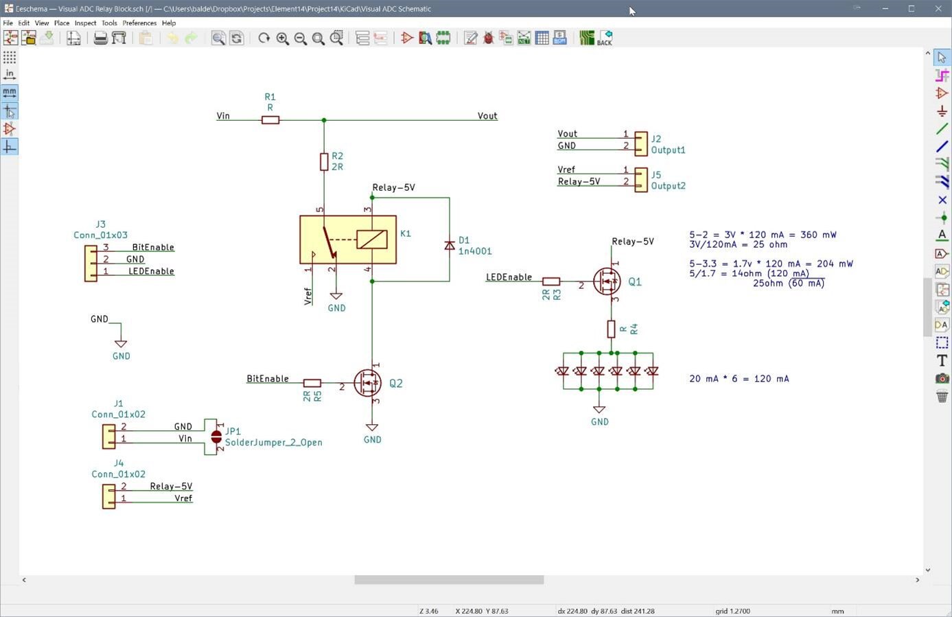
- DAC. Ironically, the most critical and visually interesting part of the Visual ADC project is the digital-to-analog converter. The idea is to create each bit of the DAC with a resistor ladder that is controlled by a relay. There will be LEDs to light-up the bit when it is active and the relays will make a nice clicky noise.
Rough Schematic
This schematic shows the overall project idea. After sketching it out, I turned my attention to the individual relay boards.

This schematic page is just the individual boards. Before changing to shift registers, I would have called it complete.  Oh well. Version two is next.
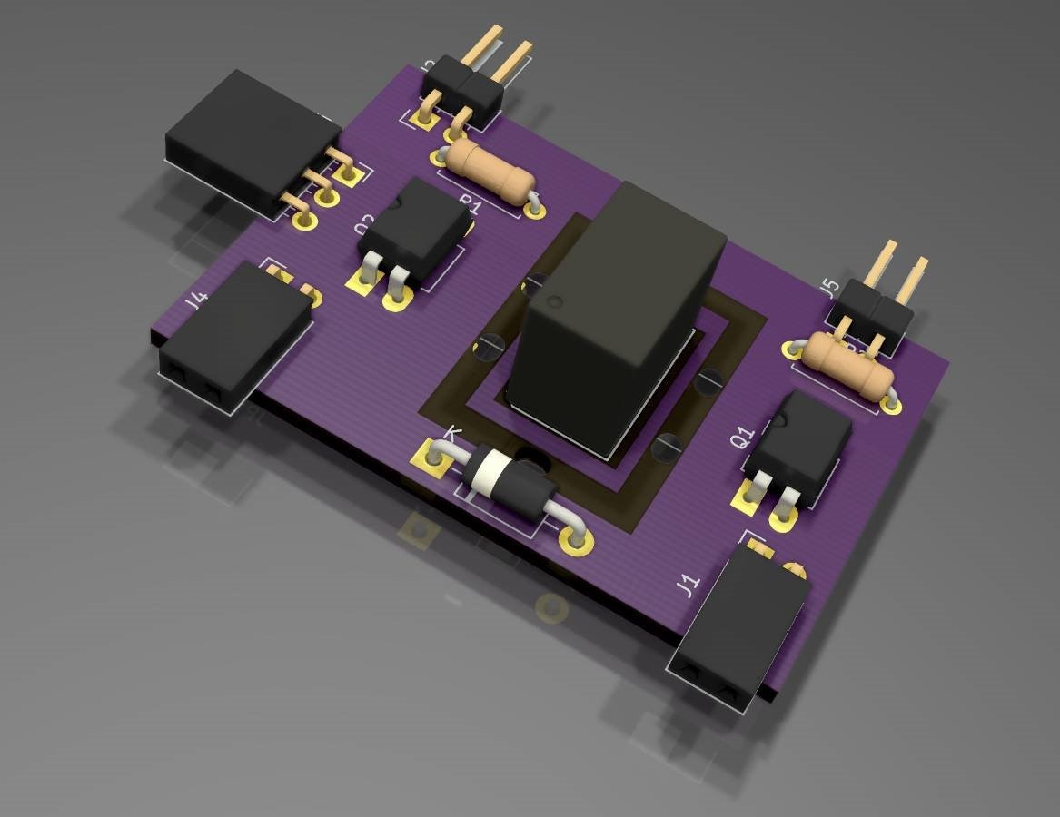
DAC Planning
Most of the planning at this point has been around the DAC. The current plan is a modular board for each bit of the DAC that gets cascaded. In the stream notes below, I mention what we accomplished on the first day of the project, which was, a lot of planning activity. One visualization trick I am trying for the first time is to use OSH Park's 4-layer PCBs with reverse mounted LEDsreverse mounted LEDs.
2021-02-07 Stream Notes
My plan is to stream the project, or at least, most of it. You can check the full stream for the initial design here. In the beginning, I explain what a SAR is and then start to draw a block diagram. That activity quickly turns into a KiCad exercise. It has been YEARS since I built an R-2R ladder, so I simulated one with iCircuit. While doing all of this work, I decided to build small modules for each bit of the ADC's DAC. To me, this is the hardest part because I need multiple copies of this circuit to get the bits of the ADC. So making a small PCB for this part of the Visual ADC means I can quickly build a 3- or 4-bit version and then scale up to more later. In fact, after the stream, one of my viewers talked me into putting a 74HCT595 74HCT595 shift register on each of these boards, to make chaining easier. Somewhere in the middle of the stream, I played with the idea of masking out the reverse LEDs. Still debating how best to do that. Most likely on the next stream, I'll be re-working this board.

Next Steps
I want to get a revision of this board off to OSH Park as soon as possible, in case it needs a second spin. The next immediate task is figuring out a plan for controlling the relays and LEDs. Initially, I thought of two MOSFETs--one for the LEDs and one for the relay. Now that I am thinking of a shift register, I am debating between a `595 and a TLC5940. If I go either of those routes, then I could individually control the LEDs. After the boards get done, my attention will turn to the sample-and-hold input stage.
Last, at some point, I'll post the KiCad files. Currently, they are a mess.