element14 Community
element14 Community
    Register Log In
  • Site
  • Search
  • Log In Register
  • About Us
  • Community Hub
    Community Hub
    • What's New on element14
    • Feedback and Support
    • Benefits of Membership
    • Personal Blogs
    • Members Area
    • Achievement Levels
  • Learn
    Learn
    • Ask an Expert
    • eBooks
    • element14 presents
    • Learning Center
    • Tech Spotlight
    • STEM Academy
    • Webinars, Training and Events
    • Learning Groups
  • Technologies
    Technologies
    • 3D Printing
    • FPGA
    • Industrial Automation
    • Internet of Things
    • Power & Energy
    • Sensors
    • Technology Groups
  • Challenges & Projects
    Challenges & Projects
    • Design Challenges
    • element14 presents Projects
    • Project14
    • Arduino Projects
    • Raspberry Pi Projects
    • Project Groups
  • Products
    Products
    • Arduino
    • Avnet Boards Community
    • Dev Tools
    • Manufacturers
    • Multicomp Pro
    • Product Groups
    • Raspberry Pi
    • RoadTests & Reviews
  • Store
    Store
    • Visit Your Store
    • Choose another store...
      • Europe
      •  Austria (German)
      •  Belgium (Dutch, French)
      •  Bulgaria (Bulgarian)
      •  Czech Republic (Czech)
      •  Denmark (Danish)
      •  Estonia (Estonian)
      •  Finland (Finnish)
      •  France (French)
      •  Germany (German)
      •  Hungary (Hungarian)
      •  Ireland
      •  Israel
      •  Italy (Italian)
      •  Latvia (Latvian)
      •  
      •  Lithuania (Lithuanian)
      •  Netherlands (Dutch)
      •  Norway (Norwegian)
      •  Poland (Polish)
      •  Portugal (Portuguese)
      •  Romania (Romanian)
      •  Russia (Russian)
      •  Slovakia (Slovak)
      •  Slovenia (Slovenian)
      •  Spain (Spanish)
      •  Sweden (Swedish)
      •  Switzerland(German, French)
      •  Turkey (Turkish)
      •  United Kingdom
      • Asia Pacific
      •  Australia
      •  China
      •  Hong Kong
      •  India
      •  Korea (Korean)
      •  Malaysia
      •  New Zealand
      •  Philippines
      •  Singapore
      •  Taiwan
      •  Thailand (Thai)
      • Americas
      •  Brazil (Portuguese)
      •  Canada
      •  Mexico (Spanish)
      •  United States
      Can't find the country/region you're looking for? Visit our export site or find a local distributor.
  • Translate
  • Profile
  • Settings
DIY Test Instrumentation
  • Challenges & Projects
  • Project14
  • DIY Test Instrumentation
  • More
  • Cancel
DIY Test Instrumentation
Blog Pico Puffer
  • Blog
  • Forum
  • Documents
  • Members
  • Mentions
  • Sub-Groups
  • Tags
  • More
  • Cancel
  • New
Join DIY Test Instrumentation to participate - click to join for free!
  • Share
  • More
  • Cancel
Group Actions
  • Group RSS
  • More
  • Cancel
Engagement
  • Author Author: scottiebabe
  • Date Created: 10 Aug 2021 3:26 AM Date Created
  • Views 3801 views
  • Likes 16 likes
  • Comments 11 comments
  • diytestinstrumentationch
Related
Recommended

Pico Puffer

scottiebabe
scottiebabe
10 Aug 2021

Introducing, the Pico Puffer a high precision capacitance meter. With the name puffer being a fun adaptation of the short-form saying of pico-farads as puffs.image


My hope for this project is to be able to make a capacitive soil moisture measurement. It will also be handy for non-conductive fluid level measurements of a December indoor tree image.


It’s alive in its Frankenstein embodiment on a breadboard.

image


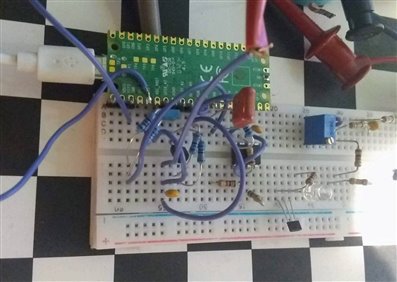
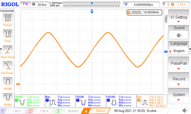
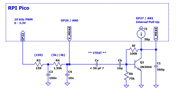
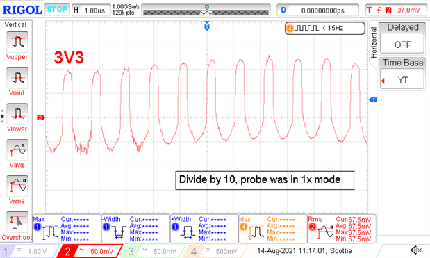
The capacitor excitation signal is derived from a 10 kHz PWM signal followed by a 2nd order RC low-pass filter. While the output isn’t a perfect sinusoid, its close enough to not to overload the TIA.

image


I was able to get the RPi Pico to round-robin DMA sample 2 inputs into a 100 kSample buffer (50 kSa each) at the full ADC sample-rate of 500 kSa/s.


image

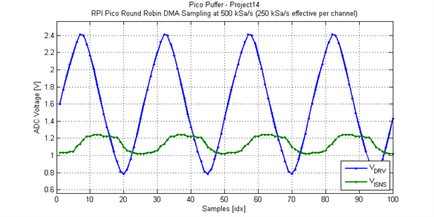
The TIA has a forward trans-resistance of approximately -100kOhms. That is why in the figure above the current signal (green) is lagging versus leading; the result is inverted.

image

Here, I had just used a 24 pF ceramic capacitor in place of measurement electrodes.


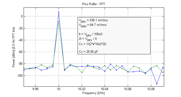
The system noise floor measuring the TIA output voltage in a 5 Hz DFT bin is approximately 20 uVrms.


image

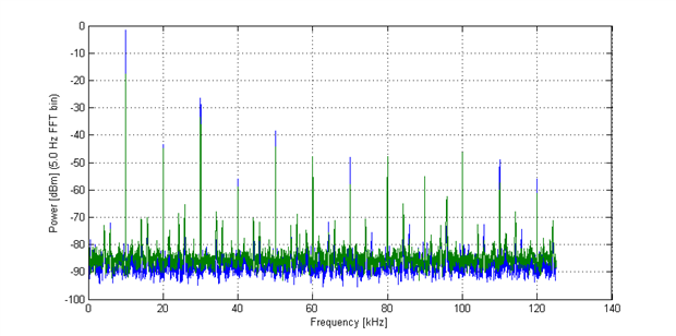
Which would put the measurement resolution at approximately 6 fF rms. I think that should be just fine.


Now to put it all together. For the spectral analysis I will use the Goertzel algorithm to estimate 1 DFT bin. I have already tried this python implementation https://gist.github.com/sebpiq/4128537 on the Pico with good results.


Schematic

image


Breadboard to Perfboard


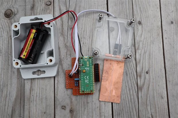
I was able to fit the Pico Puffer into a Bud Industries outdoor rated enclosure.

image


One step closer to measuring soil moisture content.


The Lost Digit

This is still a work in progress. At present, I am not achieving the measurement resolution I was hoping for, the noise is upwards of 500 uVrms sampling either the excitation signal or TIA output. Even more disheartening is the noise does not scale with the digital process gain of longer sample records. There are a number potential aggressors which could be at fault.


I added 2 additional 10 uF 16V MLCC to the 3v3 rail on the RPI Pico to further reduce the output ripple of the DCDC converter from 7 mVrms to 2 mVrms:

imageimage


The ADC input to the excitation signal is clean as it has a 10 nF output capacitor from the 2nd order RC low-pass filter. The ADC input from the TIA was suffering from charge injection from the SAR ADC's input sample capacitator:

image

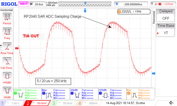
The addition of a 560 pF bypass capacitor on the TIA output provides a low source impedance to the ADC's input during its sample window. Additionally, the 560 pF bypass capacitor doesn't reduce the effective bandwidth or stability of the TIA.


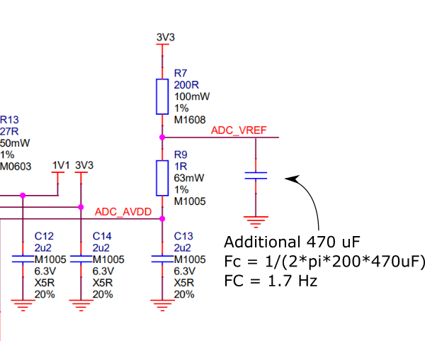
An additional 470 uF electrolytic filter capacitor was added to the ADC reference supply rail:

image


When I sample either the excitation signal or TIA output with my 34401A34401A in ACV with a 200 Hz measurement bandwidth I do not see millivolt excursions in AC amplitude.

image

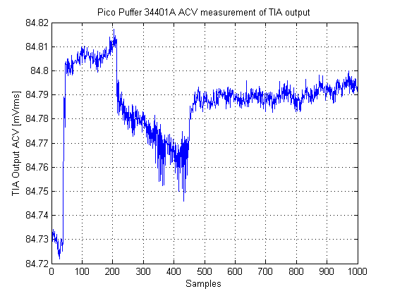
If you bump or breathe too closely to the Pico Puffer you will see a measurement variation. But, the output refereed noise of the TIA in a 200 Hz bandwidth is in the low microvolts not millivolts.


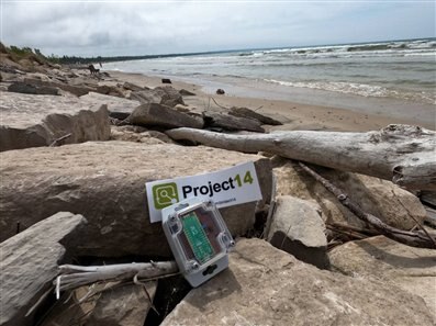
The Pico Puffer took a few day trip to the beach before the summer passes.

image


Test Electrodes

As a first pass attempt I just used a piece of copper clad FR4 scored to create to parallel electrodes. The dimensions of each electrode are approximately 1.5 cm x 7 cm.


The plastic shield bag is not a good choice for measurement repeatability, the air gap between the bag and electrodes can vary with time causing the effective capacitance to vary.


image

Fluid Level Sensing

When the electrode are dry they have a baseline capacitance of 7.8 pF. As the fluid (water in this case) submerges some fraction of the electrode the fringing electric field lines between the two electrode see the dielectric constant of the fluid versus air resulting in a higher effective capacitance. When the electrodes are fully submerged in water the effective capacitance increases to 37 pF.


You don't have permission to edit metadata of this video.
Edit media
x
image
Upload Preview
image


Soil Moisture Sensing


Originally, I had planned to try and calibrate the copper-clad test electrode. Unfortunately, the cling-film insulator I had used sprung a leak and the test was cut short.


image


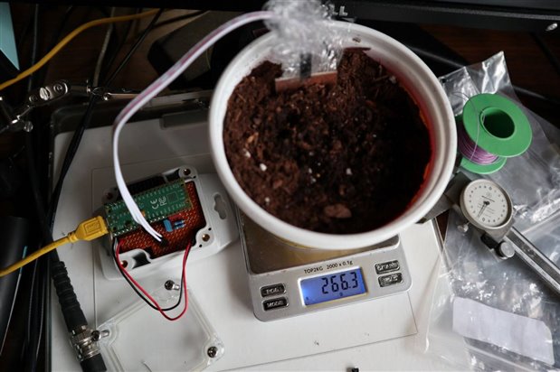
The sensitivity using a sheet of cling-film as an insulator was very impressive, until it leaked and overloaded the TIA. But, I did get a nice graph before leak occurred.

image

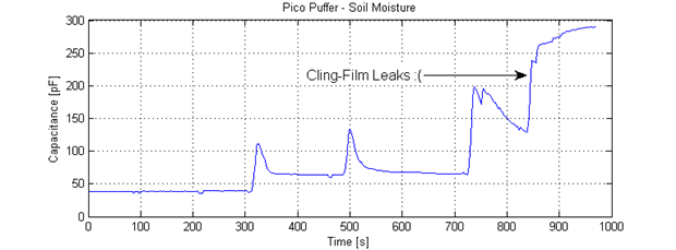
Table of when water was added to the container.


Time [s]Weight [g]
0142.7 (Dry)
120163.8
210204.1
300266.4
500301.7
700352.1


  • Sign in to reply

Top Comments

  • dougw
    dougw over 4 years ago +6
    Cool application. That kind of sensitivity will allow the system to detect a person walking by. Is stray capacitance going to cause problems?
  • michaelkellett
    michaelkellett over 4 years ago +5
    I did a similar thing a while ago, I wanted to measure crosstalk between electrodes in an electrostatic printhead at the end of a 5m multicore cable. The cost of bits didn't matter much so I generated…
  • michaelkellett
    michaelkellett over 4 years ago in reply to scottiebabe +3
    scottiebabe wrote: That is fascinating, 5m is a long distance I would think to run the electrode signals. That must be one big printer:) It's an ink jet printer with remote head - the kind of thing that…
Parents
  • michaelkellett
    michaelkellett over 4 years ago

    I did a similar thing a while ago, I wanted to measure crosstalk between electrodes in an electrostatic printhead at the end of a 5m multicore cable.

    The cost of bits didn't matter much so I generated my sine wave with an AD DDS chip.

    I used the ADC on an ST processor. The key to getting a good result, with the least calculation, is to sample synchronously with the sine wave - you need a minimum of 3 samples

    per sine cycle but I used more (8 or 10 I think).

    Because each amplitude measurement effectivley averages thousands of samples the 12 bit converter could still give more than 80dB dynamic range.


    From your plots I think you are already sampling synchronously  - it took a fair bit of juggling with settings on the processor timers and ADC to get the DDS synched up - it was clocked with a timer

    pulse from the processor.


    Will you post a schematic some time - that would be nice.


    (One day I'll work out why the spelling checker doesn't work for me in E14 image - I think I've fixed all the typos)


    MK

    • Cancel
    • Vote Up +5 Vote Down
    • Sign in to reply
    • More
    • Cancel
  • scottiebabe
    scottiebabe over 4 years ago in reply to michaelkellett

    That is fascinating, 5m is a long distance I would think to run the electrode signals. That must be one big printer:)


    Your advice for synchronous sampling is wise. Since the PWM excitation signal and ADC sample clock are both derived from the system clock the 2 clock are phase coherent. I just needed to ensure that I sample an integer number of excitation cycles. Otherwise I would have spectral spreading in the DFT 

    imageimage

    Still not perfect with a hanning window. I am trying to keep the processing load down for the Pico, as python isn't that fast. I want to avoid FFT windowing, so I took the effort to ensure I got an exact 10kHz excitation clock.


    Here is the schematic of what I breadboarded. I may still modify some component values when I put the circuit on perfboard.

    image

    • Cancel
    • Vote Up +2 Vote Down
    • Sign in to reply
    • More
    • Cancel
Comment
  • scottiebabe
    scottiebabe over 4 years ago in reply to michaelkellett

    That is fascinating, 5m is a long distance I would think to run the electrode signals. That must be one big printer:)


    Your advice for synchronous sampling is wise. Since the PWM excitation signal and ADC sample clock are both derived from the system clock the 2 clock are phase coherent. I just needed to ensure that I sample an integer number of excitation cycles. Otherwise I would have spectral spreading in the DFT 

    imageimage

    Still not perfect with a hanning window. I am trying to keep the processing load down for the Pico, as python isn't that fast. I want to avoid FFT windowing, so I took the effort to ensure I got an exact 10kHz excitation clock.


    Here is the schematic of what I breadboarded. I may still modify some component values when I put the circuit on perfboard.

    image

    • Cancel
    • Vote Up +2 Vote Down
    • Sign in to reply
    • More
    • Cancel
Children
  • michaelkellett
    michaelkellett over 4 years ago in reply to scottiebabe

    scottiebabe  wrote:


    That is fascinating, 5m is a long distance I would think to run the electrode signals. That must be one big printer:)


    It's an ink jet printer with remote head - the kind of thing that can print on boxes on a conveyor belt as they whiz past.

    Not cheap !


    Some of the signals are buffered at the remote end.

    MK

    • Cancel
    • Vote Up +3 Vote Down
    • Sign in to reply
    • More
    • Cancel
element14 Community

element14 is the first online community specifically for engineers. Connect with your peers and get expert answers to your questions.

  • Members
  • Learn
  • Technologies
  • Challenges & Projects
  • Products
  • Store
  • About Us
  • Feedback & Support
  • FAQs
  • Terms of Use
  • Privacy Policy
  • Legal and Copyright Notices
  • Sitemap
  • Cookies

An Avnet Company © 2025 Premier Farnell Limited. All Rights Reserved.

Premier Farnell Ltd, registered in England and Wales (no 00876412), registered office: Farnell House, Forge Lane, Leeds LS12 2NE.

ICP 备案号 10220084.

Follow element14

  • X
  • Facebook
  • linkedin
  • YouTube