


For the DIY Test Instrument Project14 Challenge I decided that I wanted to make something using a graphic display and something I have been playing with this summer (when the sun actually shines!) are solar cells. Solar cells are interesting things as the power they produce is very dependent on the sunshine 'power', naturally, which affects the maximum power transfer point. The maximum power transfer load occurs when the load resistance across the solar cell is the same as the internal resistance of the solar cell and the internal resistance varies depending on the intensity of the sunshine falling on the solar cell. So it seemed to me that a meter that would measure and display the maximum power transfer and the maximum power transfer load resistance would be a good thing. So here it is.
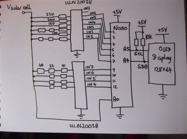
Circuit Diagram
The circuit consists of a Nano connected to a 128x64 OLED white display which is used to show text and graphics. Ten of the Nano digital outputs are used to control analogue switches (ULN2003A) capable of a maximum current of 500 mA, used to apply resistive loads from 44 Ohms upto 220 Ohms. I didn't have all the specific resistor values I wanted so I made them up out of the values I did have. (Note : Buying lower value pin-thro-hole resistors is quite difficult if you only want a few). The values I managed were:
44 Ohms (22 + 22)
57 Ohms (10 + 47)
69 Ohms (22 + 47)
79 Ohms (10 + 22 + 47)
91 Ohms (22 + 22 + 47)
100 Ohms
122 Ohms (22 + 100)
150 Ohms
200 Ohms
220 Ohms
I used Veroboard to construct the circuit, aiming for as few additional wires as possible, which is why the circuit is a bit 'odd' in places. In the end I think I only used four wires, plus the components, which seemed pretty good to me.
The circuit works by applying one of the resistive loads across the connected solar cell for a short period of 20 mA. I only had 250 mW resistors so a short applied load period was sensible, in order to avoid overheating the resistors, and I choose 20 ms. Solar cells are essentially semiconductors so should have short rise times and 20 ms seemed a good amount. I didn't have time to experiment with alternative delay values and the resistors did not seem to warm up. The solar cell voltage, Vsolar, is then measured using A0 on the Nano. In order to calculate the current through the load resistor I needed to subtract the Vbe voltage of the ULN2003AULN2003A transistors switches from Vsolar and then divide by the resistor value. Rather than try and measure the Vbe one each resistor load I took a sequence of manual measurement's using a DVM at various loads and decided that a value of 0.65V would be sufficiently accurate. The current can then be calculated as:
I solar = (Vsolar - Vbe)/R
and the power becomes
Psolar = Vsolar x Isolar
for each value of resistor.
To make a nice display on the OLED display it would be preferable to have more than 10 values (one for each different resistive load). Additional values can be obtained by fitting a polynomial curve to the power values. A library exists to do this in Arduino called CurveFitting which is easy to install via the Library Manager.
Sadly, it transpires that the Nano does not seem to have enough data memory to be able to implement both the OLED display and the curve fitting process as when both are implemented the same programme became unstable, resetting and just producing rubbish. There was insufficient time to rework the hardware circuit using an Arduino with a larger memory (I did try the programme using a Maker WAN1310 and it seemed to work but it was not a pin for pin replacement for the Nano) so I ended up with two separate programmes. One obtains the power values, the other determines the polynomial coefficients. So I manually typed the power values into the curve fitting programme, obtained the coefficients and then manually entered them back into the first programme. I managed to get a working result although not in 'real-time'. It would only take a bit more time and effort to rework the hardware to use the Maker WAN1310 (or some other Arduino with more memory) to create a fully working real-time measurement system.
The programme listing for the power collection part (with the graphic display part as well), is listed below. It is a bit long as the output bits controlling the resistor loads are handled explicitly rather than using a for loop, as the outputs used are not all sequential - due to the hardware construction. But, it works. It is also possible that not all of this programme is actually needed - there were many iterations.
/* Solar Cell DVM
Displays the Characteristic of a small solar cell
Dubbie Dubbie 13th Aug'21
Just for Fun
Uses an OLED 128x64 (clone of Adafruit display) with I2C with SSD1306
driver and the Adafruit library. (or is it SPI?)
GND = GND
VCC = 5V
SCL = A5
SDA = A4
10 kOhm resistors between A4-5V and A5-5V remove some problems with the I2C bus.
It doesn't seem to work without these (sometimes!)
*/
#include <Adafruit_GFX.h> // Include core graphics library for the display
#include <Adafruit_SSD1306.h> // Include Adafruit_SSD1306 library to drive the display
Adafruit_SSD1306 display(128, 64); // Create display 128x64
#define displaywidth 128
#define displayheight 64
#define text_delay 500
#define LED 13
#define SCinput 0 // Analogue input bit for solar cell voltage
#define VbeVoltage 129 // Digital value of 0.63V (Vbe of ULN2003AULN2003A driver)
#define loadondelay 20 // Time resistive load is powered for measurements
#define in1 2 // 220 Ohm
#define in2 3
#define in3 4
#define in4 5
#define in5 6 // 100 Ohm
#define in6 7
#define in7 9
#define in8 10
#define in9 11
#define in10 12
double x[] = {45.5, 54.0, 59.4, 65.2, 71.6, 77.0, 90.3, 101.6, 108.8, 98.9};
// Coefficients obtained from a separate programme
double coeffs[] = {-0.00002328, 0.00639639, 0.01055579, 35.644};
void setup()
{
pinMode(LED_BUILTIN, OUTPUT);
pinMode(in1, OUTPUT);
pinMode(in2, OUTPUT);
pinMode(in3, OUTPUT);
pinMode(in4, OUTPUT);
pinMode(in5, OUTPUT);
pinMode(in6, OUTPUT);
pinMode(in7, OUTPUT);
pinMode(in8, OUTPUT);
pinMode(in9, OUTPUT);
pinMode(in10, OUTPUT);
digitalWrite(in1, LOW); // Make sure all resistor loads are off
digitalWrite(in2, LOW);
digitalWrite(in3, LOW);
digitalWrite(in4, LOW);
digitalWrite(in5, LOW);
digitalWrite(in6, LOW);
digitalWrite(in7, LOW);
digitalWrite(in8, LOW);
digitalWrite(in9, LOW);
digitalWrite(in10, LOW);
delay(100); // Display initialisation delay
display.begin(SSD1306_SWITCHCAPVCC, 0x3C); // Not entirely sure what this does
display.clearDisplay(); // Clear the buffer
display.setTextColor(WHITE); // Set color of the text
display.setRotation(0); // Set orientation. Goes from 0, 1, 2 or 3
pinMode(LED, OUTPUT);
Serial.begin(9600);
Serial.println("Solar Cell DVM Awake ");
} /*setup */
void loop()
{
int value;
value = 0;
Serial.println("Starting SCDVM ");
Serial.println("Made by Dubbie, Just for Fun " );
Serial.println();
delay(text_delay);
display.clearDisplay(); // Clear the display so we can refresh
display.setCursor(0, 10); // Bottom left
display.println("Dubbie Dubbie ");
display.println("Solar DVM");
display.println(" ");
display.display(); // This outputs to the screen
delay(1000);
display.clearDisplay();
display.display();
measureVIP(); // Measure power curve
plotpowercurve(); // Display power curve
while(1)
{
} /* while */
} /* loop */
double getSCV(int load)
{
int SCvoltage;
SCvoltage = 0;
digitalWrite(load, HIGH);
delayMicroseconds(loadondelay); // Short on delay for voltages to satablise
SCvoltage = analogRead(SCinput);
digitalWrite(load, LOW); // Turn off to avoid over heating
return ((5.0 * SCvoltage)/1023.0); // Convert to floating point voltage
} /* getSCV */
double getSCI(int load)
{
double SCI;
SCI = 0.0;
SCI = getSCV(load) - 0.65; // Get voltage across resistor
// Now convert to mA : I = V/R * 1000
switch(load)
{
case in1 : SCI = (SCI/220.0) * 1000.0; break;
case in2 : SCI = (SCI/200.0) * 1000.0; break;
case in3 : SCI = (SCI/150.0) * 1000.0; break;
case in4 : SCI = (SCI/122.0) * 1000.0; break;
case in5 : SCI = (SCI/100.0) * 1000.0; break;
case in6 : SCI = (SCI/91.0) * 1000.0; break;
case in7 : SCI = (SCI/79.0) * 1000.0; break;
case in8 : SCI = (SCI/69.0) * 1000.0; break;
case in9 : SCI = (SCI/57.0) * 1000.0; break;
case in10 : SCI = (SCI/44.0) * 1000.0; break;
default : SCI = -1.0; // Use negatives as an error
} /* switch */
return (SCI);
} /* getSCI */
void measureVIP()
{
int index;
index = 0;
x[0] = getSCV(in1) * getSCI(in1);
x[1] = getSCV(in2) * getSCI(in2);
x[2] = getSCV(in3) * getSCI(in3);
x[3] = getSCV(in4) * getSCI(in4);
x[4] = getSCV(in5) * getSCI(in5);
x[5] = getSCV(in6) * getSCI(in6);
x[6] = getSCV(in7) * getSCI(in7);
x[7] = getSCV(in8) * getSCI(in8);
x[8] = getSCV(in9) * getSCI(in9);
x[9] = getSCV(in10) * getSCI(in10);
// This is a fix to ensure the same results everytime
x[0] = 45.5;
x[1] = 54.0;
x[2] = 59.4;
x[3] = 65.2;
x[4] = 71.6;
x[5] = 77.0;
x[6] = 90.3;
x[7] = 101.6;
x[8] = 108.8;
x[9] = 98.9;
for (index = 0; index < 10; index++)
{
Serial.print("P = ");
Serial.print(x[index]);
Serial.println(" mW ");
} /* for */
Serial.println();
// delay(5000); // Delay to see values
} /* measureVIP */
void plotpowercurve(void)
{
int x, y;
double xval = 0.0;
int maxyval;
int yval; int colour;
x = 0; y = 0;
yval = 0;
colour = 1;
maxyval = 0;
display.clearDisplay(); // Clear the display
display.setCursor(0, 10); // Bottom left
display.println("Calculating Power Curve ");
display.println("Please wait .... ");
display.println(" ");
display.display(); // This outputs to the screen
delay(1000);
display.clearDisplay(); // Clear the display
// Get the maximum y value - needed for scaling the display
for (x = 0; x < 123; x++)
{
xval = 44.0 + ((x * 176.0)/127.0);
yval = calcy(xval);
if (yval > maxyval) // Need the largest value for scaling the display
{
maxyval = yval;
} /* if */
} /* for */
// Now recalculate the y values and plot
// Needed as there isn't enough RAM in the Nano
for (x = 0; x < 128; x++)
{
xval = 44.0 + ((x * 176.0)/127.0);
yval = calcy(xval);
y = ((yval * 63) / maxyval);
display.drawPixel(x, (63 - y), colour);
} /* for */
// Show max power transfer load value
display.setCursor(80, 50); // Bottom right
display.print("R = ");
display.print(maxyval);
display.display(); // Display the curve
} /* plotpowercurve */
double calcy(double xval )
{
double yval;
yval = 0.0;
// Use the curve coefficients to calculate value
yval = coeffs[0] * xval * xval * xval;
yval = yval + (coeffs[1] * xval * xval);
yval = yval + (coeffs[2] * xval);
yval = yval + coeffs[3];
return(yval);
} // calcy
The programme for performing the curve fitting is listed below and is based on the example programme supplied with the library. Both programmes were 'hacked' about a great deal while I was trying to get them working, so there are probably many poor techniques and inefficiencies, plus some unnecessary code. But, they did produce the desired results, eventually!
#include <curveFitting.h>
#include <Adafruit_GFX.h> // Include core graphics library for the display
#include <Adafruit_SSD1306.h> // Include Adafruit_SSD1306 library to drive the display
Adafruit_SSD1306 display(128, 64); // Create display 128x64
void setup()
{
delay(100); // Display initialisation delay
display.begin(SSD1306_SWITCHCAPVCC, 0x3C); // Not entirely sure what this does
display.clearDisplay(); // Clear the buffer
display.setTextColor(WHITE); // Set color of the text
display.setRotation(0); // Set orientation. Goes from 0, 1, 2 or 3
Serial.begin(9600);
while(!Serial);
Serial.println("Starting");
display.clearDisplay(); // Clear the display so we can refresh
display.setCursor(0, 10); // Bottom left
display.println("Dubbie Dubbie ");
display.display(); // This outputs to the screen
char buf[100];
int xpower = 3;
int order = 3;
snprintf(buf, 100, "Fitting curve of order %i to data of power %i...\n", order, xpower);
Serial.print(buf);
double x[] = {45.5, 54.0, 59.4, 65.2, 71.6, 77.0, 90.3, 101.6, 108.8, 98.9};
double t[] = {44.0, 57.0, 69.0, 79.0, 91.0, 100.0, 122.0, 150.0, 200.0, 220.0};
double coeffs[order+1];
int ret = fitCurve(order, sizeof(x)/sizeof(double), t, x, sizeof(coeffs)/sizeof(double), coeffs);
if (ret == 0){ //Returned value is 0 if no error
char c = 'a';
Serial.println("Coefficients are");
Serial.println();
for (int i = 0; i < sizeof(coeffs)/sizeof(double); i++)
{
Serial.print(c); c++; Serial.print(" = ");
Serial.print(coeffs[i],8);
Serial.print('\t');
} /* for */
Serial.println();
}
}/* setup */
void loop(void)
{
} /* loop */
To get the final results I took the hardware outside in the slightly sunny afternoon and obtained a set of power values. Then returned back inside, typed these power values into the curve fitting programme, obtained the polynomial coefficients and then typed these back into the original programme. The results for all this effort is illustrated in the video below. A nice curve and the maximum power transfer resistor load.
Demonstration Video
Summary.
I am satisfied that the concept of the Solar Cell DVM (should this be DPM) is valid and workable, once the problem of needing more data memory for the floating point calculations and graphic display are sorted, probably with a MakerWAN1310 or similar. It will then be possible to monitor the changing maxim power transfer point of individual solar cell, as the sun varies in intensity.
I was planning to make a 3D printed casing but this was not started due to the problems outlined above.
Dubbie
Top Comments