


I really should be doing other things, but I can't resist doing another quick piece of DIY Test Equipment. Again I'm
going to post it here in my blog. I haven't worked it up into a polished piece of equipment - it isn't even really
finished - instead I'm piecing together a design that you could take 'as is' and finish nicely or use the building
blocks for something quite different.
This time it's a diode tester. Operation is quite simple: I'm going to pass a current through the diode and measure the
forward voltage across it. The current will be controlled by the processor and the voltage read by the processor's ADC. I
only intend it for signal diodes and LEDs, so the current will only go up to 50mA (it would be possible to adapt it for
higher currents if you wanted to, but you'd have to look carefully at the power dissipation of the transistor). I'm going
to rely on the person doing the test to get the diode the right way round and not try to sense and correct for that with
the circuit. For the kind of diodes you'd test with this, they'd all stand 5V reverse voltage (the lowest are usually LEDs,
but they are generally specced at 5V or 6V maximum reverse voltage).
Here's the circuit that I pieced together in the simulator. (The ammeter is there so that I can see the current - for the
built circuit, replace it with a wire.)

And here it is built on a breadboard

I've chosen the op-amps on the less-than-scientific basis that I happened to have some, they're in DIL packages, and
they're cheap. This is a dual op-amp; the two devices are in a single 8-pin DIP package and share the supply pins. You
could substitute something with a more appropriate spec if you wanted to. The main disadvantage of these is that, though
they'll operate down to a supply of 3V (which means they'll be fine on the Arduino's 5V) and they will more or less reach
ground on the input and output, they fall 1.5V short of the positive rail on both input and output. That's a limitation of
many older bipolar op-amps, although it's fine in this case as it doesn't affect the circuit I've come up with.
To understand the circuit let's divide it into three sections. Firstly, the PWM output from the Arduino is smoothed by a
simple second-order filter made up of R2, C1, R3, and C2. The resistor on the output of the filter
means that it will reduce the voltage of the PWM (5V) to a range of a tenth of that (0-0.5V at the input of the op-amp). A
disadvantage of using PWM like this, rather than a DAC, is that there will be quite a long settling time, but that's ok as
long as we're aware of it and take it into account when writing the software.
Next there is a precision current sink. The feedback around U1 controls the transistor to make the voltage across R1, the
current sense resistor, the same as the input voltage. With a 10 ohm resistor for R1, an input range of 0-0.5V will give a
current of 0-50mA, with the current being proportional to that input voltage. Since the collector current is almost the
same as the emitter current (within 0.5%, or so), that means the current through the diode will be proportionally
controlled by the PWM. [I could have done better here with a MOSFET - feel free to substitute one if you want, but make
sure its threshold voltage is quite low.]
Finally, there is a differential amplifier made from U2. This amplifies the difference in potential between the two ends
of the diode. In fact, I've chosen the resistors to only give unity gain, so the voltage out [relative to ground] will be
the same as the potential across the diode. Because of the limitation on the range of the output of the op-amp, that will
only get us up to 3.5V. I decided I could live with that - I'm not going to be testing many diodes that would have a forward
voltage of greater than 3.5V with only 50mA of current flowing through them, the only diodes that will get up to that would
be blue, green or white LEDs and you wouldn't normally run them at 50mA anyway.
That all works fine in the simulator. The next step is to build it and see what it does in practice. I've written a sketch
to sweep the PWM from 0 to 255 so we can look at the waveforms on an oscilloscope.
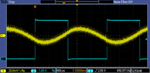
This first trace shows the PWM and the ripple after the filter. The filter isn't perfect and the lowish repetition rate of the PWM
on the Arduino isn't helping. That ripple represents about 8% of the fullscale current, so there's no way I can claim this to be
precision instrumentation. It could be improved either by increasing the PWM rate, increasing the amount of filtering, or by moving
away from the PWM and using a DAC to control the current. Something that saves me a bit is that the non-linear characteristic
of the diode means that there's much less ripple at the output. So this isn't a commercial design that you'd sell, but it's ok as
a very cheap circuit, with few bits, that you can throw together quickly and will do something useful and allow you to experiment
with hardware. [If you wanted to try a DAC version, consider either a PSoC device or some of the ST parts that have built-in DACs.]
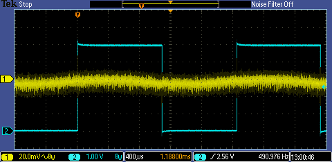
Ripple on the output voltage
This trace shows the voltage at the input of U1 [yellow trace], as generated by the PWM, and the voltage at the output [blue trace].
This is with a 1N4148 as the device under test. You can see the non-linear characteristic of the diode quite
clearly. (You can also see the way that the yellow trace fattens halfway up where the ripple is at its worst.)
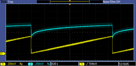
Now a trace with a blue LED as the DUT [device under test]. Here the forward voltage is much higher.

If you look at the higher current end of the trace, you can see where the forward voltage has flattened at about 3.6V. That's
where the output of the op-amp has reached its limit - if you substituted a part with a 'rail-to-rail' output, you'd get the rest of that curve.
The output voltage can be read by the Arduino's ADC and there are several ways this could function as a tester. One way would
be to have a selection of 'spot' currents that could be selected or cycled round. For testing LEDs, currents of 5mA, 10mA,
15mA, 20mA, would allow the brightness to be assessed as well as giving the forward voltage at commonly used currents.
A more ambitious instrument could sweep the input and plot the curve. I'll leave all that as an exercise for the
reader. It would also be quite simple to build a version that didn't use the processor at all - a potentiometer at the
input to set the current and a meter to read the diode voltage would do, with the whole thing operating off of a battery.
Finally, and rather belatedly, here's the very simple code that sweeps the PWM:
int pwmout = 3;               // the PWM pin used for output
int pwm_output_value = 0;     // PWM output value
// the setup routine runs once when you press reset:
void setup() {
  // declare pin 9 to be an output:
  pinMode(pwmout, OUTPUT);
}
// the loop routine runs over and over again forever:
void loop() {
  // write to the PWM output
  analogWrite(pwmout, pwm_output_value);
  // change the value for next time through the loop:
  pwm_output_value = pwm_output_value + 1;
  // reset when we get to max value
  if (pwm_output_value == 255) {
    pwm_output_value= 0;
  }
  // wait for 2 milliseconds
  delay(100);
}
If you found this interesting and would like to see more of the blogs I've written, a list can be found here: jc2048 Blog Index
Top Comments