element14 Community
element14 Community
    Register Log In
  • Site
  • Search
  • Log In Register
  • Members
    Members
    • Benefits of Membership
    • Achievement Levels
    • Members Area
    • Personal Blogs
    • Feedback and Support
    • What's New on element14
  • Learn
    Learn
    • Learning Center
    • eBooks
    • STEM Academy
    • Webinars, Training and Events
    • More
  • Technologies
    Technologies
    • 3D Printing
    • FPGA
    • Industrial Automation
    • Internet of Things
    • Power & Energy
    • Sensors
    • More
  • Challenges & Projects
    Challenges & Projects
    • Design Challenges
    • element14 presents
    • Project14
    • Arduino Projects
    • Raspberry Pi Projects
    • More
  • Products
    Products
    • Arduino
    • Dev Tools
    • Manufacturers
    • Raspberry Pi
    • RoadTests & Reviews
    • Avnet Boards Community
    • More
  • Store
    Store
    • Visit Your Store
    • Choose Another Store
      • Europe
      •  Austria (German)
      •  Belgium (Dutch, French)
      •  Bulgaria (Bulgarian)
      •  Czech Republic (Czech)
      •  Denmark (Danish)
      •  Estonia (Estonian)
      •  Finland (Finnish)
      •  France (French)
      •  Germany (German)
      •  Hungary (Hungarian)
      •  Ireland
      •  Israel
      •  Italy (Italian)
      •  Latvia (Latvian)
      •  
      •  Lithuania (Lithuanian)
      •  Netherlands (Dutch)
      •  Norway (Norwegian)
      •  Poland (Polish)
      •  Portugal (Portuguese)
      •  Romania (Romanian)
      •  Russia (Russian)
      •  Slovakia (Slovak)
      •  Slovenia (Slovenian)
      •  Spain (Spanish)
      •  Sweden (Swedish)
      •  Switzerland(German, French)
      •  Turkey (Turkish)
      •  United Kingdom
      • Asia Pacific
      •  Australia
      •  China
      •  Hong Kong
      •  India
      •  Korea (Korean)
      •  Malaysia
      •  New Zealand
      •  Philippines
      •  Singapore
      •  Taiwan
      •  Thailand (Thai)
      • Americas
      •  Brazil (Portuguese)
      •  Canada
      •  Mexico (Spanish)
      •  United States
      Can't find the country/region you're looking for? Visit our export site or find a local distributor.
  • Translate
  • Profile
Electromagnetism
  • Challenges & Projects
  • Project14
  • Electromagnetism
  • More
  • Cancel
Electromagnetism
Blog 3000A clamp table and amplifier update #1
  • Blog
  • Forum
  • Documents
  • Events
  • Members
  • Mentions
  • Sub-Groups
  • Tags
  • More
  • Cancel
  • New
Electromagnetism requires membership for participation - click to join
Blog Post Actions
  • Subscribe by email
  • More
  • Cancel
  • Share
  • Subscribe by email
  • More
  • Cancel
Group Actions
  • Group RSS
  • More
  • Cancel
Engagement
Author: three-phase
Date Created: 14 Apr 2019 8:56 PM
Views: 561
Likes: 5
Comments: 4
  • heat dissipation
  • clamp adapter table
  • electromagnetismch
  • current amplifier
Related
Recommended

3000A clamp table and amplifier update #1

three-phase
three-phase
14 Apr 2019

I haven't had much chance to work on the clamp table this week so it isn't quite complete, the majority of the time has been spend building and testing the current amplifier after the PCB had arrived.


For the clamp table,  I have cut some wooden legs for it and fitted them but they will need painting before final assembly. I have cut and profiled a base board for the table to sit on, this received a final coat of paint today, that is currently drying.  Five rubber feet will finish this off.


In the picture belo, the base board is on the left, with the coil table sitting on its wooden legs watching the paint dry on the base.

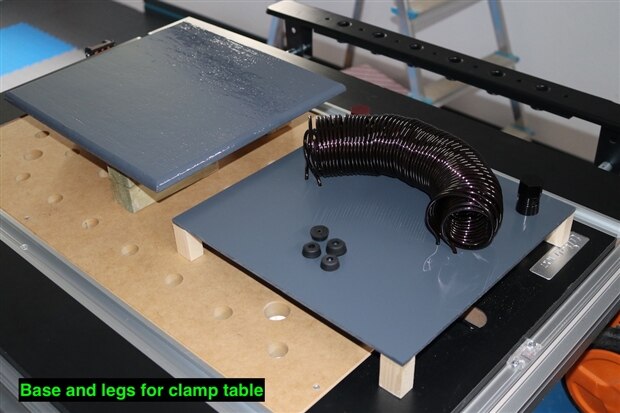
This will give the table an 'open' design, which was initially to allow heat dissipation in the original design. With the vast majority of the coil now above the surface, this isn't so critical, but I like the look of it so have kept it this way.


The PCB arrived on the Thursday, so I was keen to get it but and tested to see what issues I would have, unfortunately, there were quite a few. During the build, I had to modify the case by cutting away the bottom rail of the case sides to get the required clearances on the PCB solder joints. Two of these were at mains potential and would not have mixed to well with an aluminium case side, luckily enough it was spotted before any power was applied.


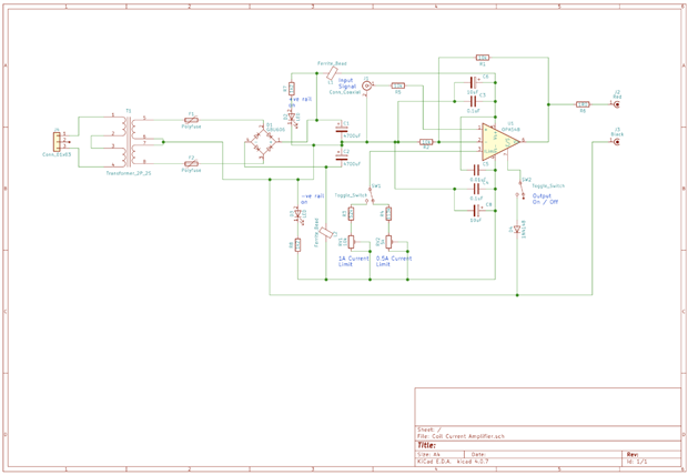
I also realised during the build, that I had made an error sizing the transformer. The 25VA rating is shared across the secondary windings, each one only having 12.5VA, so for the 9V, I would not be able to draw the originally desired 2A. Instead, I modified the selector resistors so that the amplifier had 0.5A and 1A settings, this just involved changing the value of R4 to 113kOhm. I also took this opportunity to change the output resistor from 2R2 to 1R0 to reduce the wattage rating required.


The amplifier assembled reasonably well after that, although it is a tight squeeze into the case as seen above.


Testing the amplifier, also produced issues. The 1A current rating could not be achieved, despite adjustment of the potentiometer. I am not sure what is causing this, as the 0.5A setting could be achieved and the calculations for the values were made in the same manner, just with the different current rating. I will drop the value of R3 resistor down around 10kOhms to see if this gives the correct adjustment range.


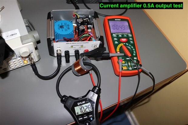
Both output current tests were made with a 20 turn coil installed on the output. This should have given a 10A and then 20A reading on the clamp meter respectively.


Temperature tests were then carried out, and caused me some concern, as on the 0.5A output, the temperature of the amplifier ramped up very quickly and I decided to switch off when it hit 50 Degrees C and kept climbing.


I decided to modify the heatsink set up by bridging between the installed heatsink and the aluminium case side, using a spare heatsink cut down to suit and thermal paste between the components. To do this meant a bit more modification to the case side to create a flat surface for the bridging heat sink.


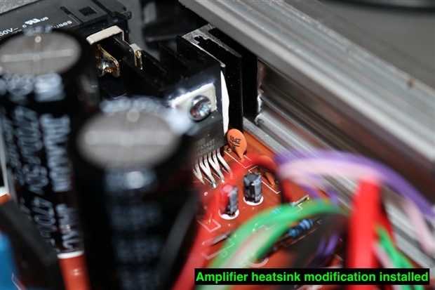
You can just see the additional heatsink in the picture with the thermal paste applied. Testing of this modification showed a stable temperature of 48 Degrees C on the 0.5A output setting, which I was much more comfortable with. In the next thermal photo, you can see the heat being transferred over to the case.


Going back and reading the data sheet for the OPA548 amplifier, it seems I might have been a little too cautious, as I think it can handle more temperature than I gave it credit for.


This completes all of the testing I have done at the moment. In principle the design seems to work, but I would like to resolve the 1A current setting before I move onto testing the frequency response of the amplifier.

Anonymous

Top Comments

  • shabaz
    shabaz over 3 years ago +2

    Hi Donald,


    That's a really great looking design, extremely well constructed!

    48 degrees C seems completely fine for room temperature use. Incidentally I recently bought a battery-powered lawnmower (Bosch…

  • three-phase
    three-phase over 3 years ago in reply to shabaz +2

    Many thanks Shabaz,


    I have found that I didn't have the input voltage turned up enough to get the full 1A output out, so I have now achieved this today. Temperature goes up to circa 79 degrees C and was…

  • genebren
    genebren over 3 years ago +2

    Donald,


    Great update!  The thermal imaging is such a powerful tool.  It clearly shows the potential issues and provides a good sense of the design margins.


    Well done!


    Gene

  • three-phase
    three-phase over 3 years ago in reply to genebren

    Many thanks Gene.


    Yes the thermal cameras are great for verifying the performance of designs. I do like the hybrid style pictures that this one produces, but haven't yet figured out how to add the temperature palette as default, so I have to re-load each picture and save as a screen grab.


    Kind regards.

    • Cancel
    • Up +2 Down
    • Reply
    • More
    • Cancel
  • genebren
    genebren over 3 years ago

    Donald,


    Great update!  The thermal imaging is such a powerful tool.  It clearly shows the potential issues and provides a good sense of the design margins.


    Well done!


    Gene

    • Cancel
    • Up +2 Down
    • Reply
    • More
    • Cancel
  • three-phase
    three-phase over 3 years ago in reply to shabaz

    Many thanks Shabaz,


    I have found that I didn't have the input voltage turned up enough to get the full 1A output out, so I have now achieved this today. Temperature goes up to circa 79 degrees C and was still climbing up but very slowly. After a while the side of the case was getting towards too hot to keep your fingers on. Seems a little more thermal management may been order with a revision. I did note that it cooled down quite quickly when selected back to the 0.5A output.


    The case is from Camden Boss, they are very nice and well made, but a bit on the expensive side. The front label was made in a word processor, I usually draw straight lines, that I can define the lengths of, to position the cutouts and text in the right place. This is printed out on a laser printer, glued onto the front plate using some spray adhesive and the gloss effect is achieved by covering with a clear adhesive film.


    Clear adhesive film


    Kind regards

    • Cancel
    • Up +2 Down
    • Reply
    • More
    • Cancel
  • shabaz
    shabaz over 3 years ago

    Hi Donald,


    That's a really great looking design, extremely well constructed!

    48 degrees C seems completely fine for room temperature use. Incidentally I recently bought a battery-powered lawnmower (Bosch) and the battery charger was "interesting".

    It gets so hot, it started smelling : ) I was worried it would start smoking, and I thought it was faulty and exchanged it, but the replacement did exactly the same thing.

    I opened it up, it had a tiny heatsink, and they've sprayed on a conformal coating to protect the PCB and it is over the heatsink too, and I think that's what is smelling. Hopefully it will stop stinking after a few charge cycles.


    Also that's a nice case with the integrated heatsinks. How did you do the lettering on the front panel?

    • Cancel
    • Up +2 Down
    • Reply
    • More
    • Cancel
Element14

element14 is the first online community specifically for engineers. Connect with your peers and get expert answers to your questions.

  • Members
  • Learn
  • Technologies
  • Challenges & Projects
  • Products
  • Store
  • About Us
  • Feedback & Support
  • FAQs
  • Terms of Use
  • Privacy Policy
  • Legal and Copyright Notices
  • Sitemap
  • Cookies

An Avnet Company © 2022 Premier Farnell Limited. All Rights Reserved.

Premier Farnell Ltd, registered in England and Wales (no 00876412), registered office: Farnell House, Forge Lane, Leeds LS12 2NE.

ICP 备案号 10220084.

Follow element14

  • Facebook
  • Twitter
  • linkedin
  • YouTube