 | Enter Your Electronics & Design Project for a chance to win a $100 Shopping Cart! | Project14 Home |
| Monthly Themes | ||
| Monthly Theme Poll |
Introduction
For my entry in the electromagnetism contest, I decided to look at building some current clamp table adapters. The intention of these was to allow me to test the full-scale range of current clamps utilising my single phase injection test set. I also intended to look at trying to test the frequency range of these current clamps using a current amplifier.
The concept of this has come about due to some monitoring work that was carried out whilst energising a 132kV supply at a substation and the need to carryout transient analysis of the voltages and currents during the energisation.
I have to concede that this hasn’t gone to plan at all, so this is more of a blog of how far I have managed to get rather than a finished project.
Current clamp table
The design of the table(s), as with all engineering, is a compromise based around the electrical and physical attributes of the test clamps themselves and my limitations of manipulating copper magnet wire.
With my single phase injection test set, I can easily inject up 30A continuous and 60A short duration up to a maximum of 1kHz.
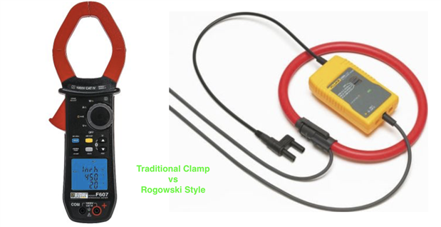
The current clamps I use can measure up to 2000A at 400Hz and up to 3000A at 20kHz. The transient analyser I have has a bandwidth of 28kHz. The physical limiting factor of the current clamps is the maximum diameter the clamp will fit around. For Rogowski style clamps, this is from 110mm to 190mm, for more traditional style clamps this down to 60mm diameter.
All of these factors affect the selection of the style of the table and the magnet wire utilised.
For continuous operation, I can inject 30A, so I would need to have a table with 100 turns to get the effect of 3000A being measured by the clamp.
Magnet wire comes in many various sizes and types. When winding electrical coils the general consensus is to work to a current rating of 750 circular mils per Amp. Under the right conditions, it is possible to push the design up to 500 circular mils per Amp. This factor is generally in relation to the temperature that the conductor will reach and the effect this temperature will have on the turn insulation around the magnet wire.
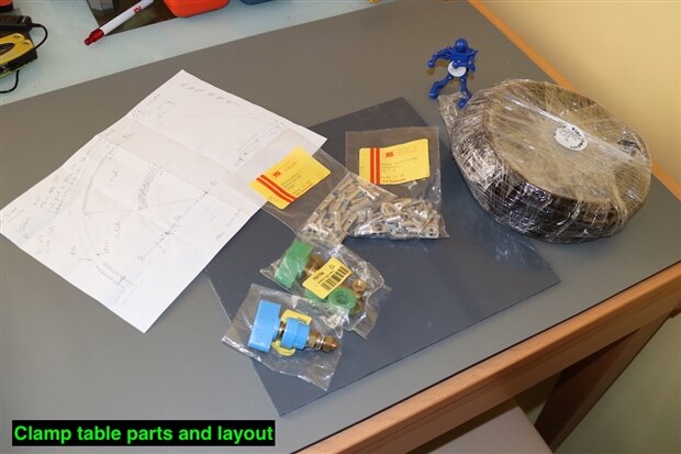
I plan to have a relatively open coil design, but due to the 100 turns required, I am planning on having one coil of 50 turns around a smaller coil of another 50 turns. This means that the inner coil will not be able to dissipate as much heat, it will also collect heat from the outer coil, especially at the bottom where the inner coil will sit on top of the outer coil. Besides, old habits die hard, so I intend to stick to around 750 circular mils per Amp.
There are a number of resources available on the internet for determining the most suitable size of magnet wire. Magnet wire, though, is more likely to be specified in diameter or length x width, so the circular mils needs to be calculated or obtained from a manufacturer’s data table.
A look at some ampacity tables from manufacturers, quickly shows that 7 AWG wire has a current carrying capacity of 30A. In the UK, the wire available to me is sold in metric diameters, so I am looking for a wire of around 3.665mm diameter. From UK suppliers, magnet wire of 3.75mm diameter is ready available, but is with a non-solderable polyester insulation, so all my joints will have to be crimped.
To see what my exact current capability will be, I can work the calculation backwards;
3.75mm diameter is equivalent to 147.638 mils (1 mil = 0.0254mm)
The cross-sectional area will be 21797 circular mils ( circular mils = diameter in mils squared)
Therefore a 750 circular mils per amp, the wire is rated to 29A, at a more aggressive 500 circular mils per amp, I would be able to push 43A through the wire, but it would get hotter.
The next size of wire up to me I found was 4.25mm diameter. Using the same method as above I can easily push 37A through this wire up to 55A maximum.
Circular mils is explained on Wikipedia; https://en.wikipedia.org/wiki/Circular_mil
There are a number of manufacturer’s data tables available;
https://www.powerstream.com/Wire_Size.htm
http://www.magnetwire.biz/magnet_wire_current.html
A good general purpose table is;
http://amasci.com/tesla/wire1.html
A couple of engineering handbooks are also worth a read;
https://www.hitachi-metals.co.jp/e/products/auto/el/pdf/MagnetWire_en.pdf
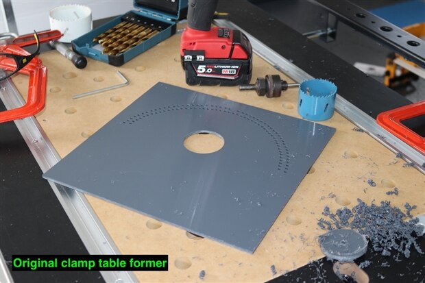
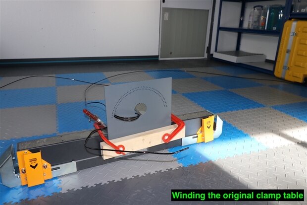
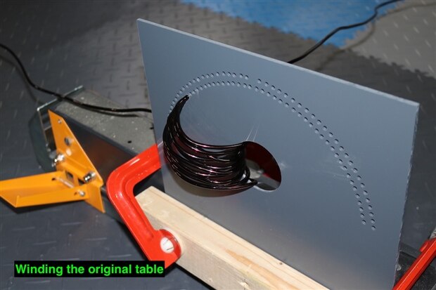
My original design was to drill out a flat plate as a former and wind the 4.25mm diameter wire, through a large central hole and then a series of individual holes to form the loops.
The smaller homes on the outside were easy to specify as 4.5mm diameter. The large central hole produces the circle packing predicament.
Wikipedia has a couple of entries on this subject;
https://en.wikipedia.org/wiki/Circle_packing
https://en.wikipedia.org/wiki/Circle_packing_in_a_circle
I also found a very useful calculator online form Engineering Tool box;
https://www.engineeringtoolbox.com/smaller-circles-in-larger-circle-d_1849.html
Based on this calculator, I needed a minimum of a 50mm circle to get 100 turns of 4.25mm magnet wire through - which actually turned out to be 4.35mm diameter when measured.
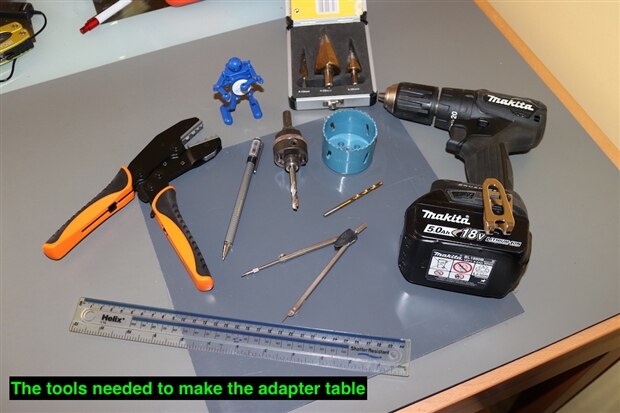
I have a 57mm diameter hole saw, which was still within my 60mm capacity of my current clamps and also gave me a little extra space to play with.
| {gallery} Original clamp adapter table |
|---|
To be honest, I should have known better than to try this, especially with my level of experience. Manipulating such a large solid diameter wire through such a former proved to be very laborious and awkward to produce neat and tidy results.
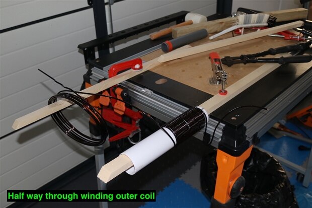
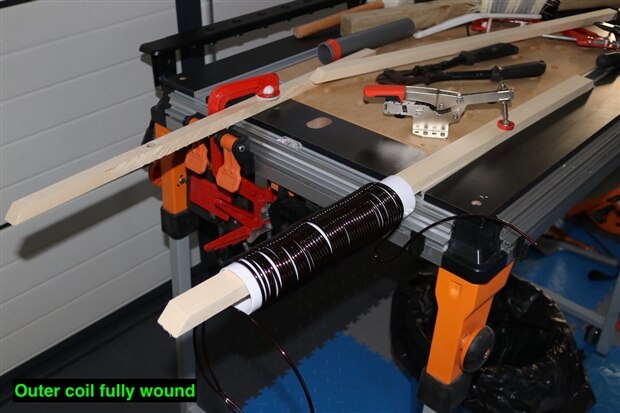
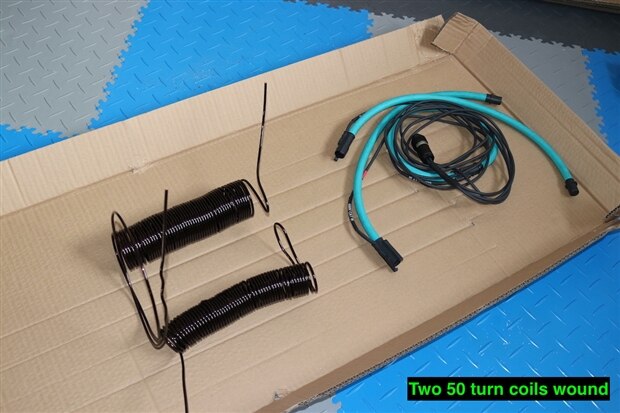
So I dispensed with this idea and moved to preforming the two coils around some plastic waste pipe. The first coil was wrapped around 40mm pipe and the second around 55mm pipe. This would then allow me to feed the smaller coil through the larger coil and connect them in series.
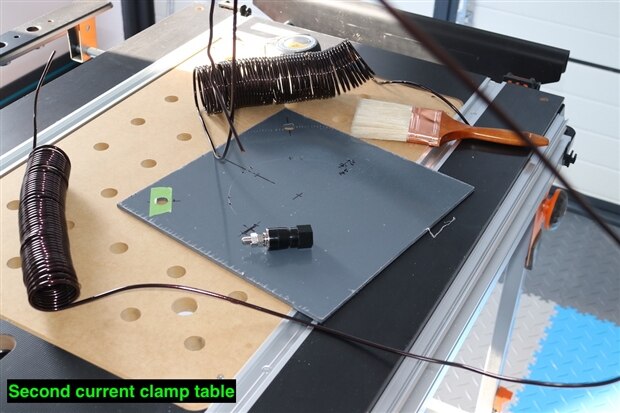
| {gallery} Second clamp adapter table |
|---|
The winding of these coils was much simpler. Assembling them onto the plate was a little awkward, but was achieved by fitting the coils inside one another and cutting the connection leads to the same length to allow them to be fed through the securing holes in the plate.
Connections to the jacks and the winding series connection were then made underneath the board. It was at this point that I realised I had wound both the coils in the same direction, so I had to make the series connection between the two different ends, and not at the same end as I had originally planned to do, as this would have cancelled out the two coils and left the clamp meter reading a net zero amps.
The other issue with this method is that I struggled with forming a tight enough curve to use the current clamp table with traditional clamps and smaller Rogowski coils. This table is therefore limited for use with the larger Rogowski coil style clamps and over time I will revisit the original design and utilise a smaller diameter wire, but increase the number of turns.
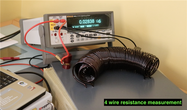
The first test on the current clamp table was to measure the DC resistance using a 4 wire method. The supplier specifies the DC resistance of the magnet wire as 1.55mOhms per meter at a temperature of 20 degrees C.
I calculated that the two coils used a total length of 14.915 meters of wire. This would give a calculated resistance of 23.1mOhms. On top of that I also have to take into account extra resistance form the two bolted and 3 crimped joints used.
The DC resistance measured at 18.6 degrees C is 28.38mOhms going across the binding posts. I then measured this as 26.77mOhms by moving the sense leads onto the the lug crimps, effectively by passing both of the binding posts, so you can start to see how the joints are affecting the resistance reading. Overall, I am happy with the resistance measurements made.
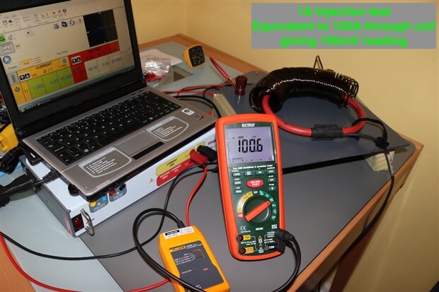
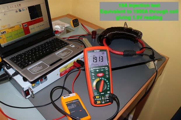
The other electrical tests carried out were with the single phase injection test and a Fluke i2000 Flex current probe.
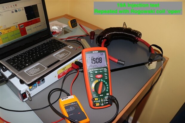
Tested initially with a multimeter, the readings were within expectations for 1A and then 19A injected, with the i2000 set to a sensitivity of 1mV per Amp.
Both of these tests showed results well within the tolerance of the i2000 Flex and the MG302 insulation multimeter. These tests were done just to show the ratio of the adapter table was correct.
It is also interesting to note that for a Rogowski coil, the coil does not actually have to be completed in order to get the reading, unlike a traditional clamp meter, where the clamp must be closed to make the magnetic circuit.
Current Amplifier
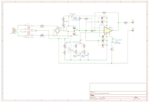
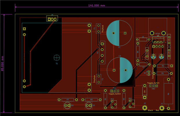
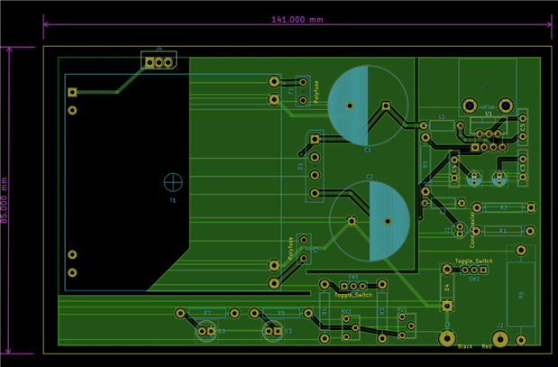
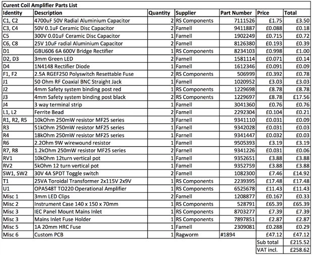
The design of the current amplifier has moved along with the schematic and PCB generated and the components required identified.
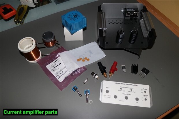
As you can see, I have started the mechanical build, having marked out and drilled the front and back plates of the case. Unfortunately, I am still missing one critical component - namely the PCB, so until this arrives the build of this cannot be progressed much further.
I have decided to utilise a OPA548 amplifier that has a built in programmable current limiter. The AC input signal will come from a waveform generator, so that I can vary the frequency as required. The intention is to have the output selectable between 1A and 2A. The original circuit had the output of the amplifier through a 2.2Ohm resistor to give some voltage load onto the amplifier, I think I will probably drop this down to a 1 Ohm resistor to reduce the wattage burden and the heat generated within the case.
The cost of the amplifier seems to have escalated a bit - primarily due to the cost of the case I used and the PCB manufacture.
As the amplifier is not very friendly for veroboard or breadboard mounting, the diagnosis has not yet been tested - so it could all go horribly wrong and require some modifications.
The output of the amplifier will be fed into the current clamp table, but I have also wound a couple of other smaller coils around some waste pipe couplers to give me some different options.
These were wound with 2.0mm diameter magnet wire so have a current limit of 2.9A. They are also physically much smaller, allowing them to be used with a wider variety of current clamps, so I think I will get some extra magnet wire and wind a larger one with more turns.


Top Comments
-

genebren
-
Cancel
-
Vote Up
+1
Vote Down
-
-
Sign in to reply
-
More
-
Cancel
Comment-

genebren
-
Cancel
-
Vote Up
+1
Vote Down
-
-
Sign in to reply
-
More
-
Cancel
Children