


Back in 2016, I completed a road test for this kit: Solar-Powered IoT Device Kit - Review
At the time, I was new to Cypress’s PSoC Creator and PSoC/PRoC BLE devices. This kit also happened to have problems with the available examples not working out the box. During the original road test, I found a workaround but, in hindsight, that too was not the correct way to resolve the problem as the solution I had worked out to clear the error messages and allow for the build and deploy would not work with PSoC Creator 4.2 and also gave problems if you updated any of the components.
So, I am now revisiting this device as I, and I’m sure others, may be thinking of using this kit for the Energy Harvesting competition.
Demonstrating the problem
Let’s recap, starting with the installation process of the relevant Device Kit SDK or “package” and then highlight the problem I’m referring to.
I've put together a short video for demo purposes (apologies once again for the poor sound quality - too much echo!). As you will see in the video, I’m using a Windows 10 PC (32 bit).
Let me now summarise...
When you install the Solar Panel IoT Device (SPID) Kit package, all files are stored here (we will return to this directory later): C:\Program Files\Cypress\Solar-Powered IoT Device Kit
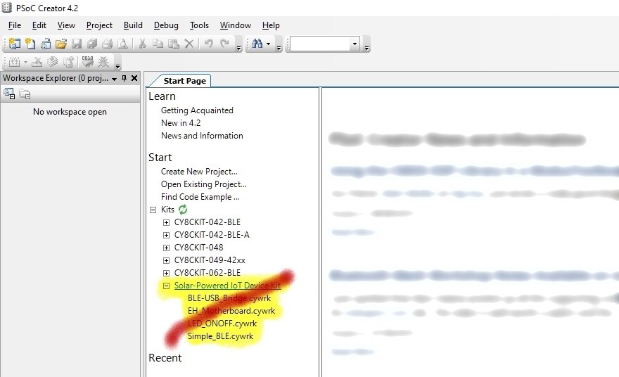
When you open up PSoC Creator, following installation of the SPID Kit package, you should have on the Start Page a new listing under “Kits”, which will provide you with a list of examples, as shown:
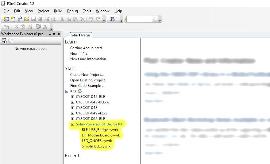
Unfortunately, if you then select to use any of the examples shown here, you will encounter problems.
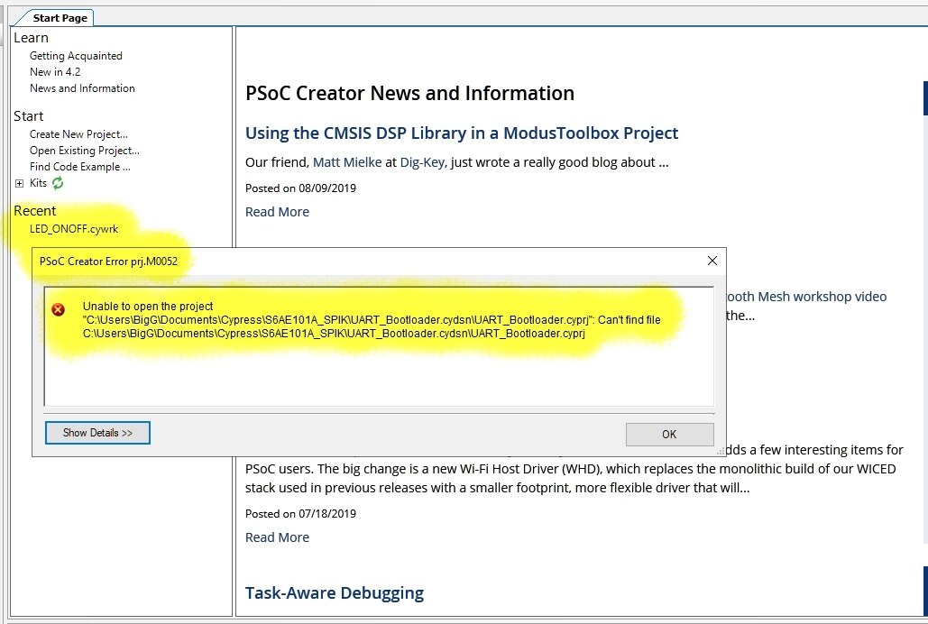
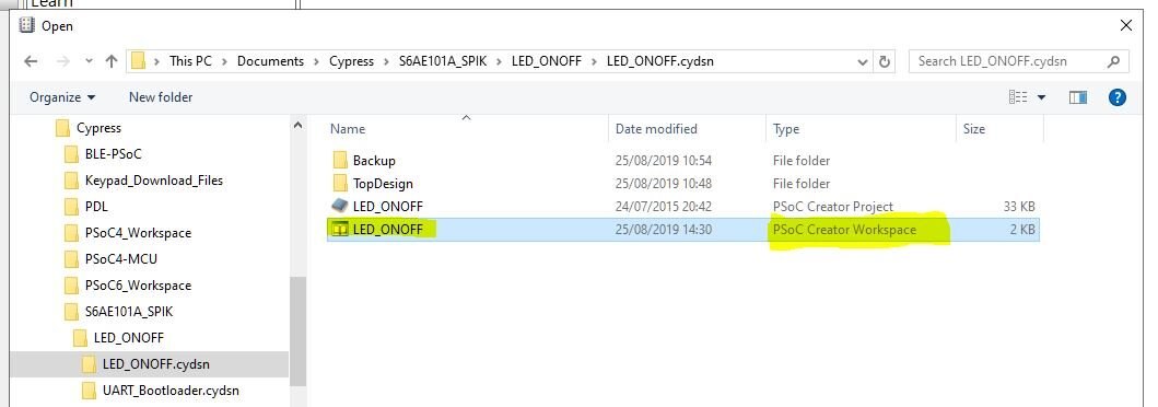
Let me use the “LED_ONOFF.cywk” example to demonstrate the issue. So, if you click on the “LED_ONOFF.cywk" you will get this dialog box noting an error:
Clicking "OK" will still open up the project. You will then get the following as your project structure (shown on left) and for your "TopDesign" you will see this:
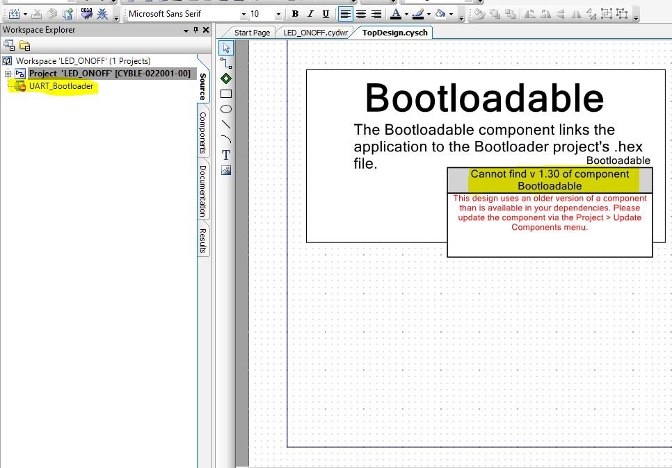
As it is quite common, when loading up old projects, to see these type of messages, we know we can normally resolve this by updating the component using the "Component Update Tool":
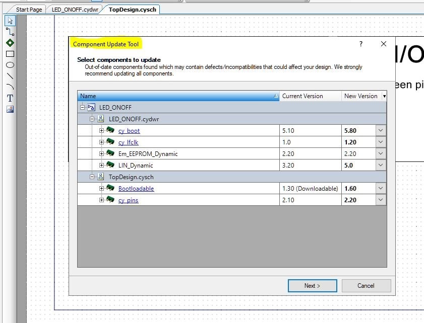
This then provides you with the latest component. As I discovered in my original road test, doing this still creates errors when building the project:
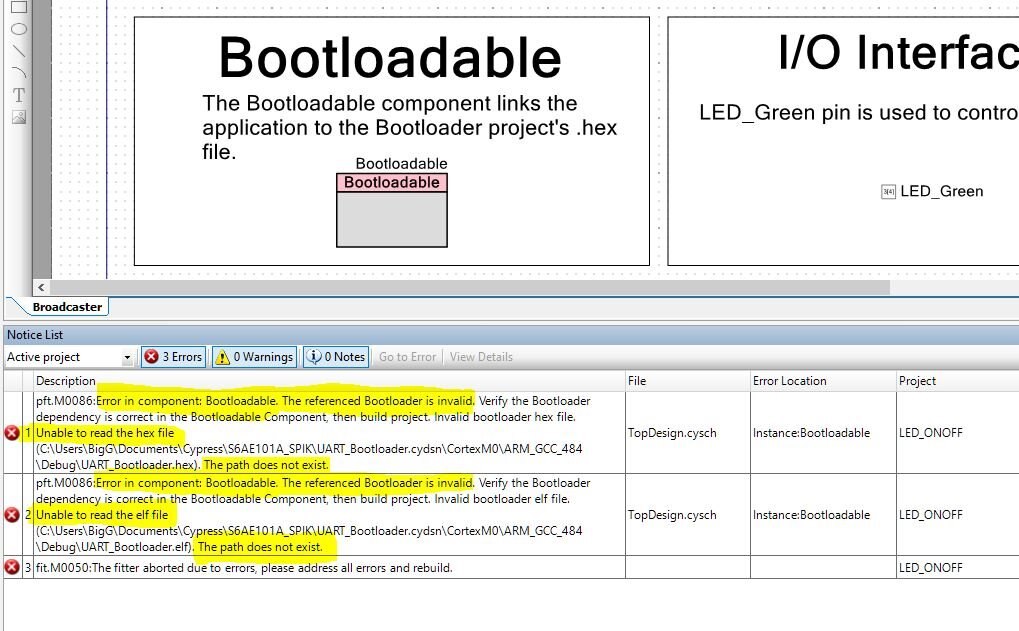
The error messages are pretty clear. The Bootloadable component is looking for a .hex and a .elf file and it cannot find those.
During my original road test I found those files in the Cypress folder within the Program Files directory and copied those across to my workspace folder and then pointed the Bootloadable component to those files. So whilst this solved the immediate problem, it was actually not the correct methodology to deploy.
Providing a workable solution
So, to understand how to do this properly, you need to understand and know how to use two components, namely Bootloader and Bootloadable. I will explain these concepts later.
Let's now demonstrate a simple workable solution.
Step 1 is to ignore this listing:
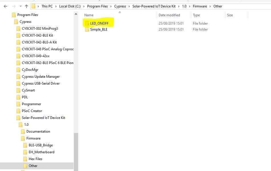
Step 2 is to use Windows File Manager and go to the "SPID Kit Firmware" folder within the "Program Files" directory to select the example you want to use:
C:\Program Files\Cypress\Solar-Powered IoT Device Kit\1.0\Firmware
The LED_ONOFF example is listed under "Other"
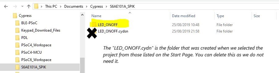
Step 3 is to copy this folder within File Manager and paste this folder into your chosen project "workspace" (usually this would be in the Documents folder)
Step 4 is to go back to Cypress PSoC Creator and select "Open Existing Project" from the Start Page or choose Open Project/Workspace from the File menu.
Find your LED_ONOFF folder within your chosen workspace and click on this folder. You will see two folders listed:
- LED_ONOFF.cydsn
- UART_Bootloader.cydsn
Now click on the "LED_ONOFF.cydsn" folder.
Step 5 is to open up the PSoC Creator Workspace file (not the Project file)
When you open up that PSoC Creator Workspace file, you should see the following:
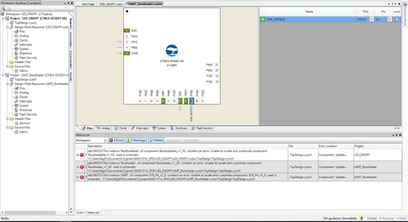
Don't worry. These error messages can be quickly resolved by updating the components using the "Component Update Tool". Once done you should see this, an error free(ish) project:
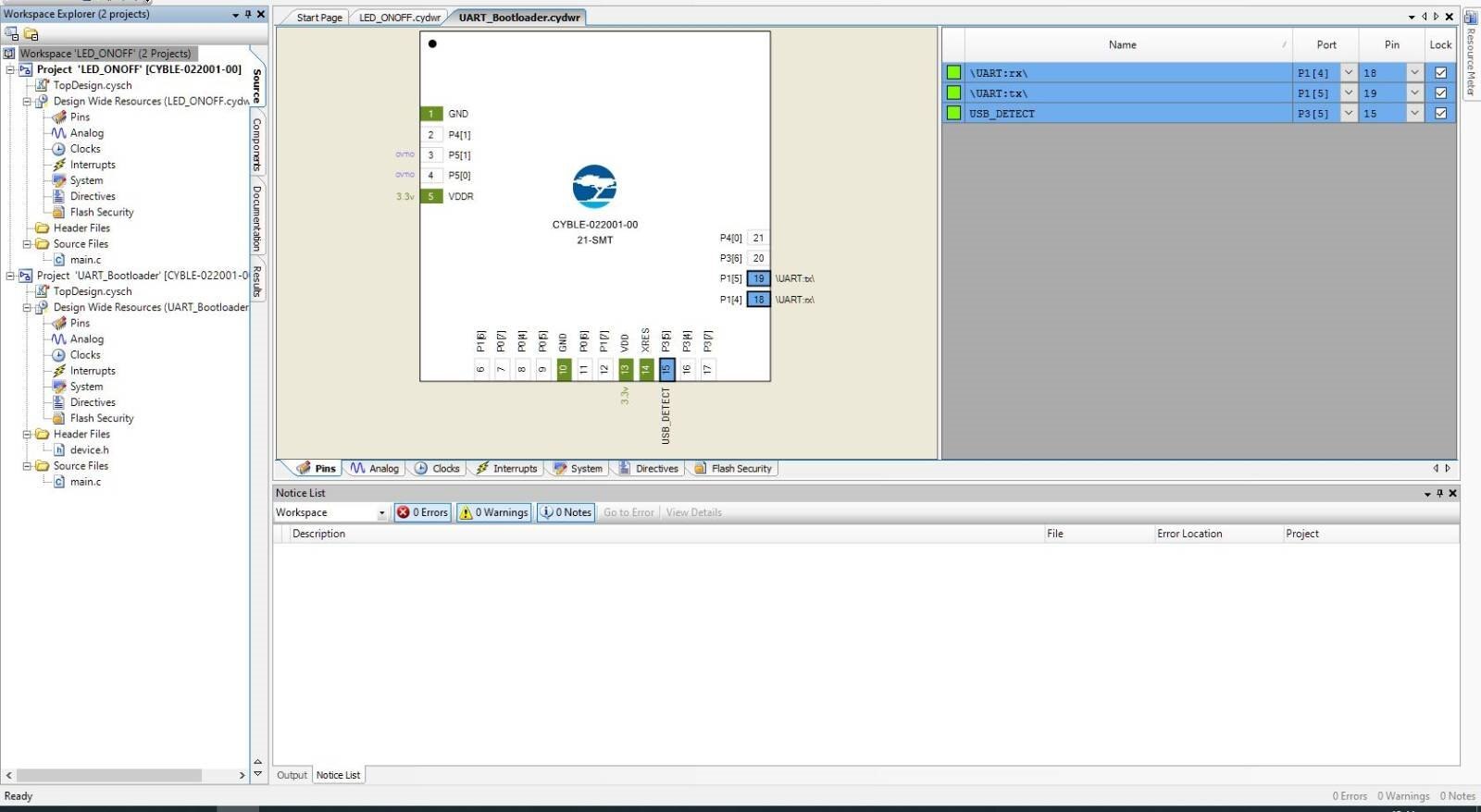
Step 6 is to "BUILD ALL Projects":
But wait... the Errors have returned!
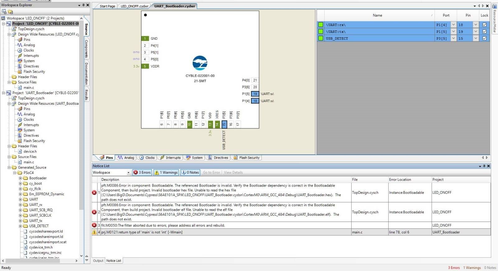
Not to worry. These can now be readily resolved by opening up the LED_ONOFF project's "TopDesign".
Step 7 is to fix the dependencies in the "Bootloadable" component by selecting the correct hex file
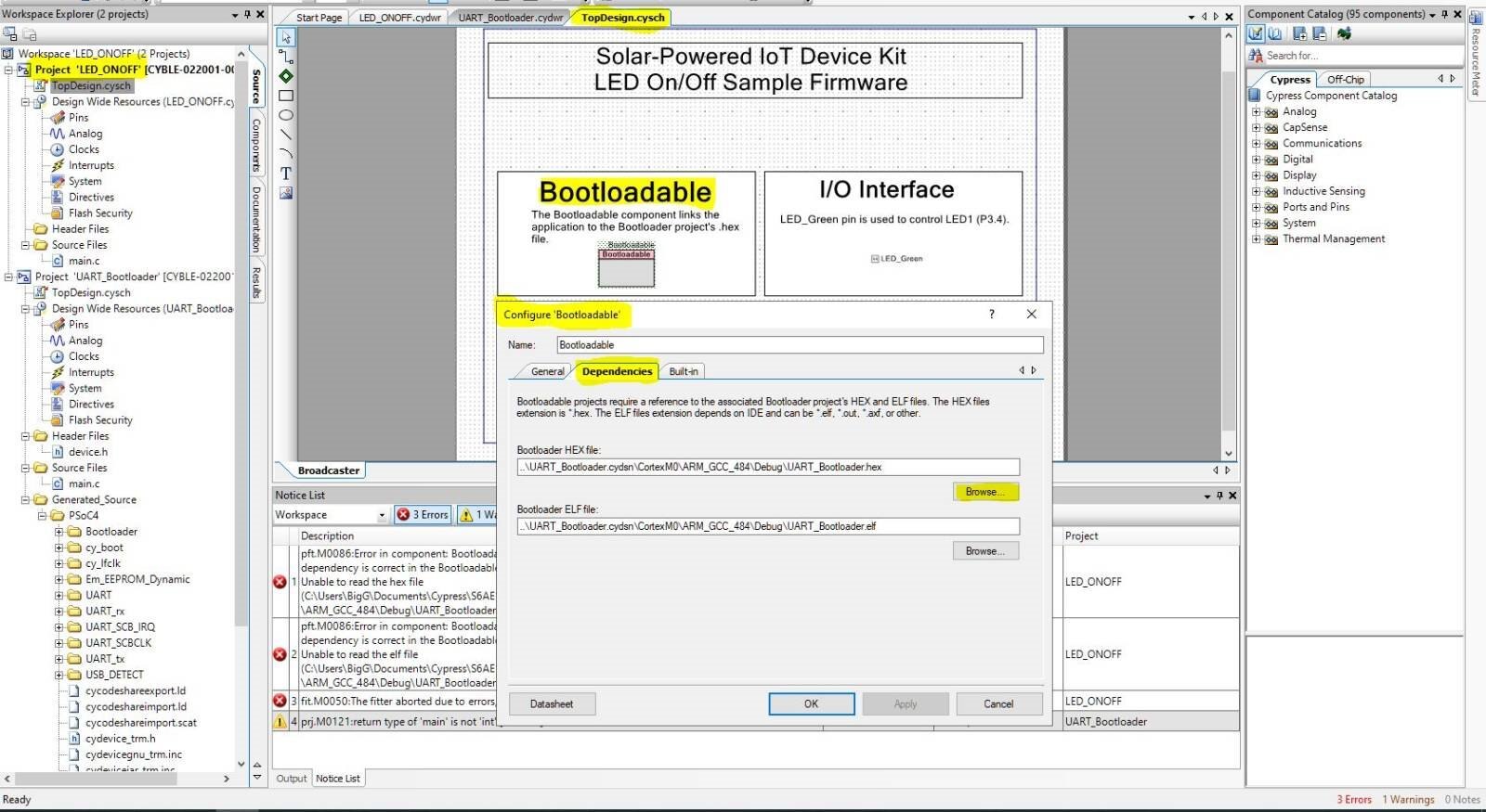
So, we double click on the "Bootloadable component" to open up the Configure dialog box and then we select the "Dependencies" tab. We now click "Browse..." to find the correct hex file.
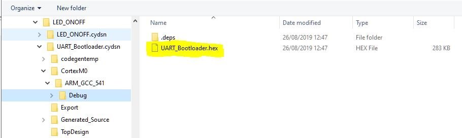
This hex file will be found within the following subfolder within "UART_Bootloader.cydsn" folder: your PSoC Creator Workspace... \LED_ONOFF\UART_Bootloader.cydsn\CortexM0\ARM_GCC_541\Debug
When you select the file and collect OK the "elf" file location will be automatically updated too.
Step 8 is to rebuild the LED_ONOFF project
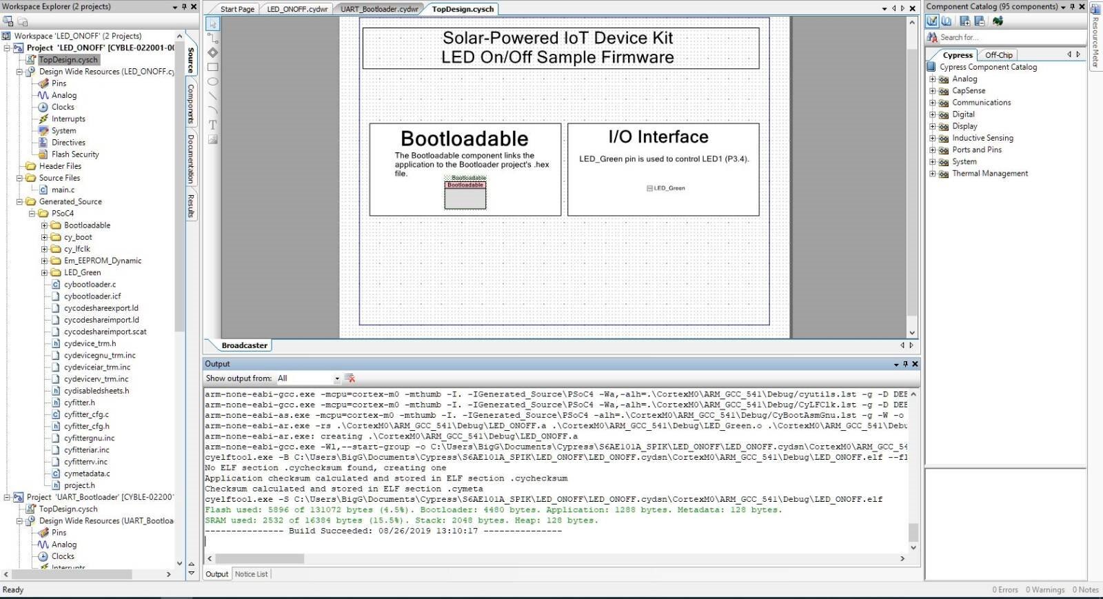
We have now successfully built the project.
Now what?
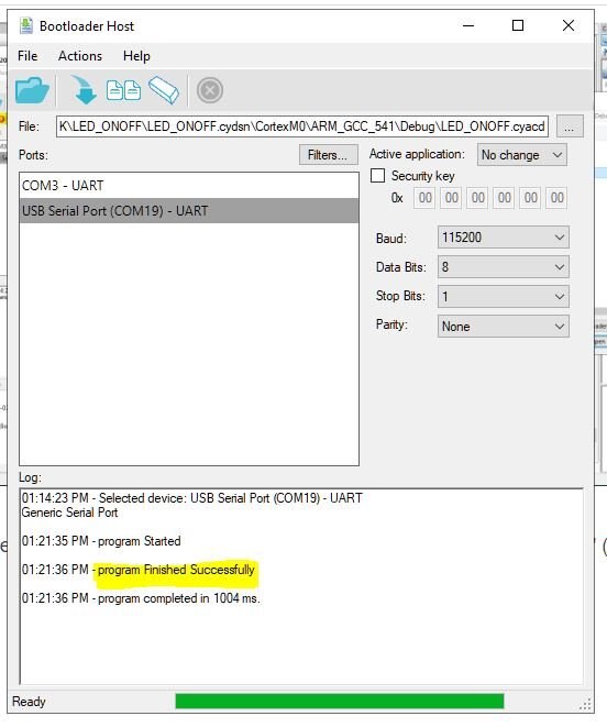
Step 9 is to open up the "Bootloader Host..." tool within the Tools menu (and don't forget to plug the USB cable into device)
You may find that the required file if not found (not always the case).
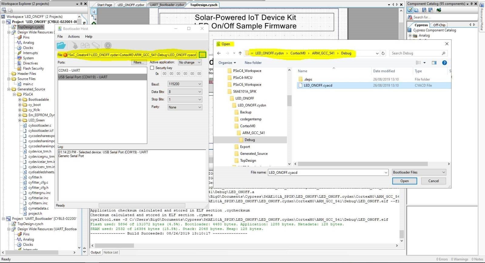
Then it is a case of pressing the device reset button and then selecting the "Program" (F5) Action. You may have to try this a couple of times to get timing right for the bootload process to kick in.
You will then get the success message (note progress bar does not completely finish and that is seen as normal).
Step 10 is to now bask in the glory, having cracked this one.
Ok, we've cracked it but it still does not explain the "how does it work".
Understanding Bootloader and Bootloadable
We’ve just seen in the LED_ONOFF example that we had to link the Bootloadable, via dependancies with a Bootloader.
So what the heck are Bootloaders and Bootloadables and how exactly do you apply these components to your PSoC Creator project for this device? Why are they in separate projects, for example?
Well, fortunately for me, Cypress Semiconductor has an excellent application note, titled “PSoC - Introduction to Bootloaders (AN73854)”, which explains these concepts and how they apply to PSoC Creator projects (phew that saves me trying to sprout bootloader theory).
So in summary then...
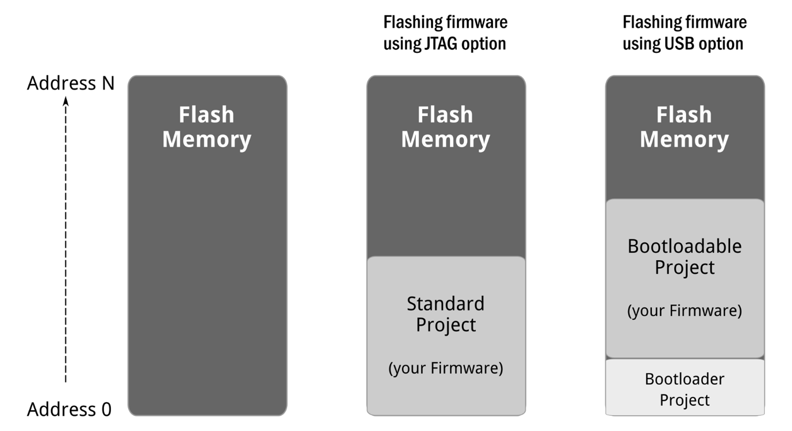
Bootloaders and Bootloadables only apply when you want to facilitate the ability to flash the device via the USB. If you wanted to only flash the device using the JTAG header, you would not need a bootloader.
So, when we want to transfer the compiled firmware from our PSoC Creator / Computer (or host) to the device (or target), the mechanism that handles the data transfer from host to target flash memory is called bootloading, or a bootload operation, or just bootload for short. The data (i.e. the firmware) that is placed in flash memory is called the application or bootloadable.
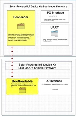
As illustrated in the diagram below, the bootloader code would usually be separate from application code. Thus it is common to see these as two separate projects, which is what we see here where each example workspace in PSoC Creator contains two separate projects or applications.
If we now refer back to the LED_ONOFF project, we can have a closer look at the separate Bootloader project. As shown in the TopDesign view, we have two components (ignore I/O interface) namely Bootloader and UART:

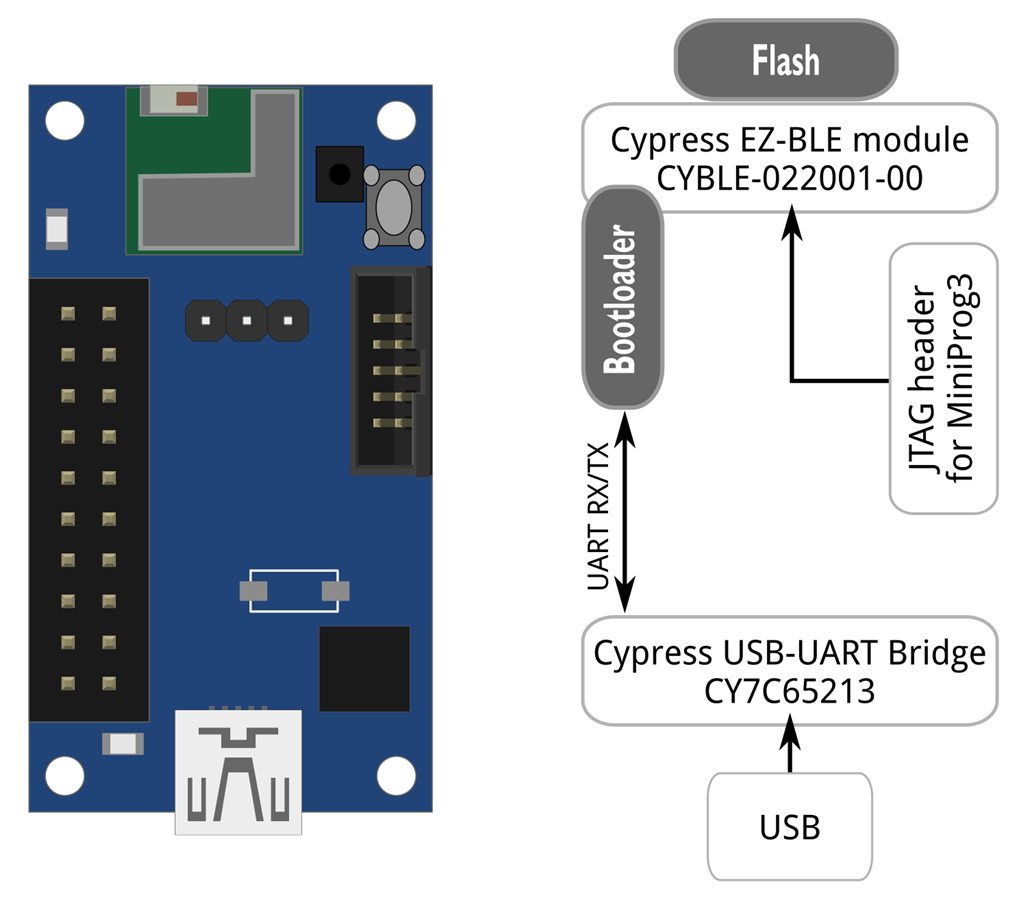
Now, you may be wondering why a UART component? To answer that question, we need to look at the device.
Here we see that there is a low-power USB to UART bridge controller (CY7C65213) and it is through this controller that we are ablte to transfer our firmware to the EZ-BLE module via UART:
If we now look at the Bootloader component, the TopDesign view has provided a nice summary “Bootloader decodes and executes the host commands. It also formulates the response packets. After successful bootload operation, the program control will be transferred to the new application firmware.” So it is our all in one command translator and command transfer handler.
If we double click on the Bootloader component we are given the configuration options.
Here you’ll notice a drop down option for Communication component which you need to set. As our device has a USB-UART bridge controller component we choose UART. Everything else is left as is.
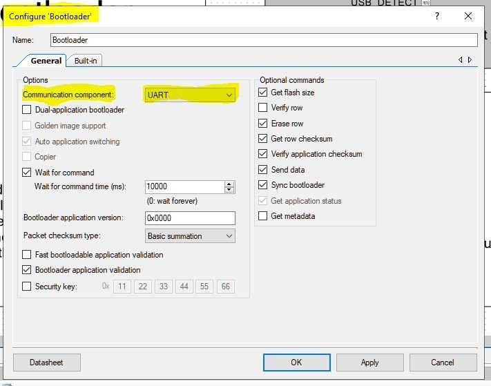
Then for the UART component, you’ll notice that the baud rate is set to 115200. Note, that this appears to differ to the Bootloader documentation which says you should use baud rate of 57600. So, I left at 115200 as it worked perfectly for me.
Then, as seen in the first video, we have to link the application project to the Bootloader and we do this by configuring the Dependencies within the Bootloadable component.
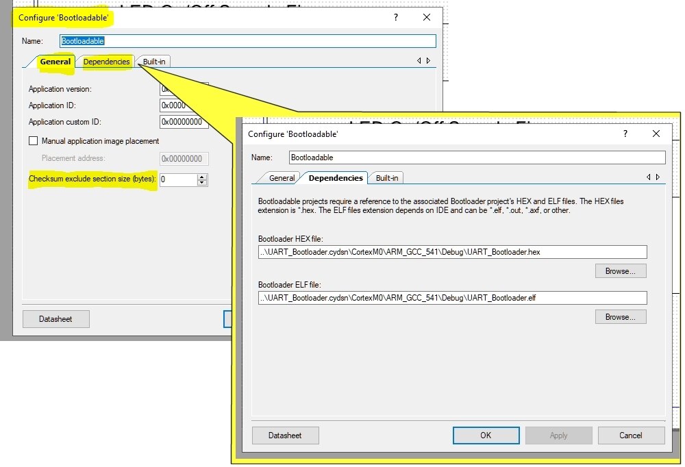
What we did not touch in the LED_ONOFF project was the “Checksum exclude section” value.
What we will see in the next video, is a demonstration of how to get the “Simple_BLE” project working.
In this video demo you will also see an error being generated, when the “Checksum exclude section” value is left as is. So, while the reason for having to change this is still unclear, this is something we have to modify (change checksum exclude section size to 1 byte) to get the project to build if we include a BLE component in our project.
In summary
Hopefully you found this tutorial useful, as this is a fantastic little device which offers great energy harvesting features.
Good luck with your next new application.
Top Comments