 | Enter Your Project for a Chance to Win a Thermal Imaging Camera, Germicidal UV Lamp, and a Shopping Cart with Matching Charity Donation! Back to homepage | Project14 Home |
| Monthly Themes | ||
| Monthly Theme Poll |
My project is EMDR tappers made with Arduino UNO. It falls under the category
Build Projects to Help You (and others) Cope!
EMDR is used by psychotherapists in the office setting to reduce patients’ stress and anxiety. And now due to Covid-19 almost everyone is stressed and anxious. Especially elder people, because it is such a high risk to die for them. One of the ways EMDR is done is by using special device called tappers, that vibrate in a patient’s hands. Right now when all the doctors and therapists work through Telehealth they cannot do EMDR because they cannot give devices to the patients. My device can be used during Telehealth sessions and it is cheap to build. I heard that tappers doctors use are crazy expensive.
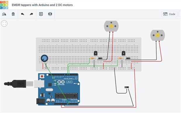
My device consist of:
Arduino UNO,
switch to turn it on/off.
2 3V DC motors, one for each tapper
2 driver circuits (transistor, resistor, diode) for driving the motors.
Potentiometer to control work frequency of tappers.
The potentiometer is connected to analog pin A0 and the value of the input from it defines how fast the motors will switch. As soon as one motor is turned off the other is turned on.
Each motor has a head of a toothbrush glued to it to brush the palm and to make it feel like a real EMDR tapper.
Driver circuits: Arduino digital pins can power devices that consume around 20 to 40mA current but 3V DC motors need high current, so I am using the transistors for driving the motors.
Transistor (PN2222) is connected in series with the motor and the transistor’s base is connected to the Arduino’s digital pin 6 through a resistance of 330 Ohm. The motor is connected between the collector pin of the transistor and the Vcc. A diode (1n4004) is connected in parallel to the motor, and it is used for blocking the reverse current.
Exactly the same setup is used for another motor controlled by digital pin 5.
_____________________________________
Source Code:
// Define Pins
#define TAPPER1 5
#define TAPPER2 6
#define KNOB_FREQUENCY A0
void setup()
{
pinMode(TAPPER1, OUTPUT);
pinMode(TAPPER2, OUTPUT);
Serial.begin(9600);
}
// main loop
void loop()
{
int delayTime = analogRead(KNOB_FREQUENCY);
delayTime = map(delayTime, 1, 1023, 1, 3000);
digitalWrite(TAPPER1, LOW);
digitalWrite(TAPPER2, HIGH);
delay(delayTime);
digitalWrite(TAPPER2, LOW);
digitalWrite(TAPPER1, HIGH);
delay(delayTime);
}
________________________________________
Attached files: image of circuit from TinkerCad, video (the same video on Youtube: https://youtu.be/8nplf5Yd7Ag )
#FightingGermsCH


Top Comments
-

ankur608
-
Cancel
-
Vote Up
+1
Vote Down
-
-
Sign in to reply
-
More
-
Cancel
Comment-

ankur608
-
Cancel
-
Vote Up
+1
Vote Down
-
-
Sign in to reply
-
More
-
Cancel
Children