


Why Connect4?
Me and my Girlfriend Sangeetha love to Play Connect4. We use it to make bets, decide on who does chores, who gets to pick the next movie, who does punishment exercise. But we did not own a board and we played it online. But It did not give the same feel. We wanted something which we can feel with our hands. Something we can play anywhere and everywhere, day or night. There is a travel version but we cant play it while lying down on the bed, and more importantly we cant play against each other when only one of us is traveling on work. I made the Version 1 for "Board Designer competition" on Hackster - https://www.hackster.io/asamakerlab/on-the-go-connect4-and-pixel-art-frame-48584d
The Version 1 Demo
We truly enjoyed the concept, but there was couple of mistakes which i made rendering the device more of a novelty game rather than the intended to go device. The second video is an updated casing. so, this time learning from my mistakes as well as usability issues i decided to make the 2nd version with the following changes/improvement
- Make the device game specific. last time i made it multipurpose (Nebula wall art and pixel frame) for a competition purpose. it still serves well for those purposes
- I want to make the device smaller. V1 PCB was around 210x210mm making it less portable and making cases on my Ender S1 Pro was very difficult, i had to hack it to print more than the standard print area
- I Dont want touch. We both prefer the haptics of a click
- Fix the battery circuit. Last time i made a mistake with battery circuitry and would only work on the USB-C cable attached. Effectively breaking the "on-the-go" function
- I want to have ESP32 to enable over the internet play as well as "LAN Play" via the ESP-Now , but will use STM32F103 as main, to conserve battery.
- I also want to make the PCB cheaper to manufacture. The 210x210mm was expensive, so this time i made it modular that way anyone who wants to recreate this, can choose any LED or LED Strip of their choice. I am gonna go with Wurth LEDs. I fell in love with them because of the seriously awesome reliability. But as i said before, you can use any other LEDs
- PCB to be made in white Solder masks, helps make the light at projection plate more uniform and hide the hotspot better.
- Improved button placement.
- I also wanted an animation of the chip falling down on the column to get a more realistic feel
And so the Concept Began
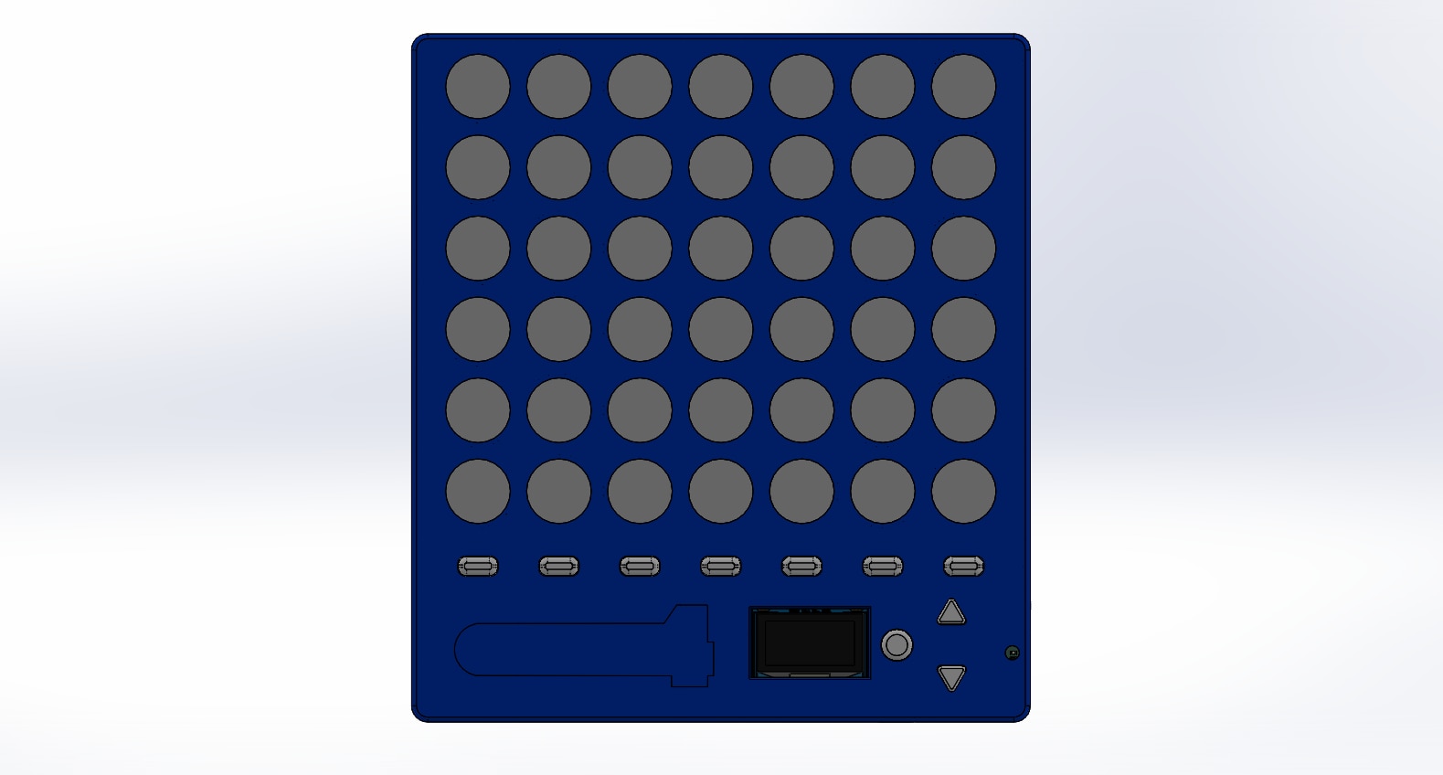
- The Buttons are now towards the right side, and can be accessed by one hand.
- The Column buttons are also easily reachable by thumbs when the hands are gripping it in both hands
- The size is around 170mmx150mm, portable yet, big enough for the feel of the game.
- A placeholder for sticker
- The Thickness is 15mm. The Restrictions come from the PCB and the Distance between the LED and diffuser needed to make an uniform Glow
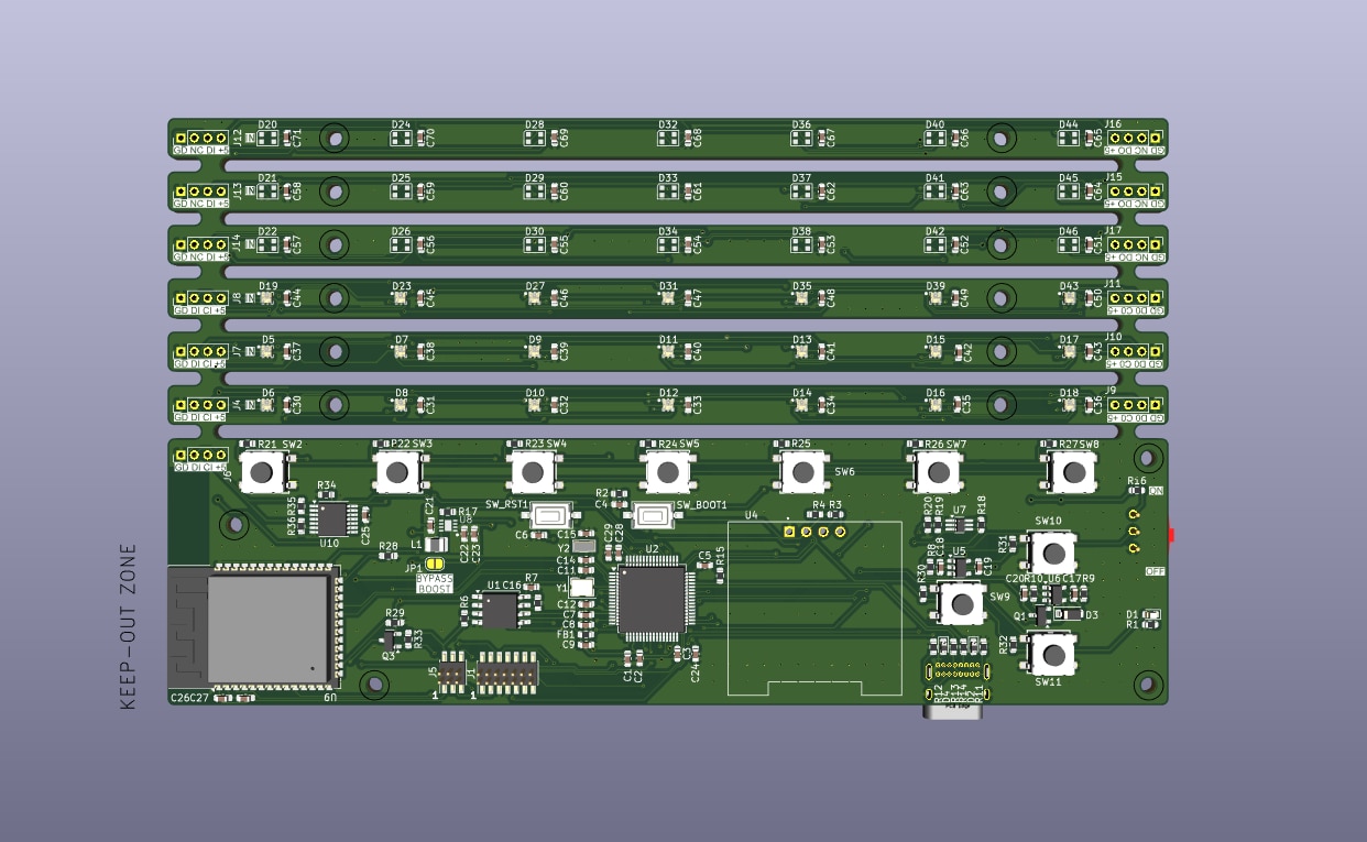
- For the PCB I made it such that there is a Control Board and LED strips. Each can be cut off and used independently.
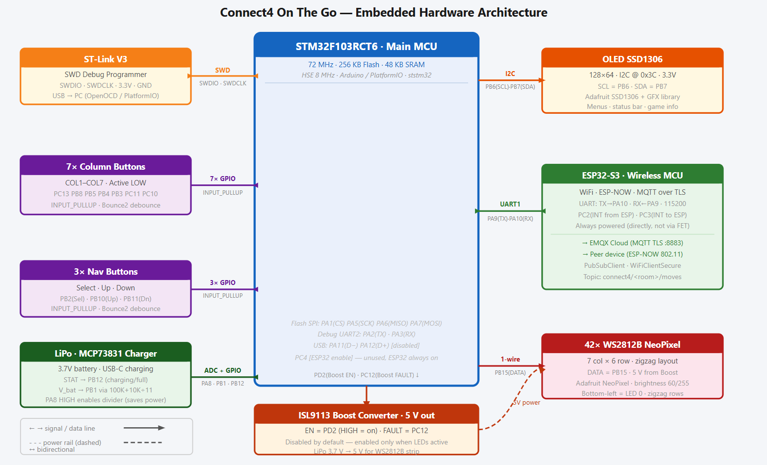
The Embedded Design
As said before the main brain is the STM32F103RCT6. I Opted STM32 because it is a healthy balance between power usage, capability and community acceptance. The ESP32-S3 works as co-processor only to transmit data via MQTT Over Internet or ESP-NOW for a local play. An MCP73831 to manage the LiPo Charging, along with Ideal FET Design for a crude power path circuit. AP2112K was a tough choice. It provided 600mA of Current before it started sagging, ESP needed a healthy 500mA during start, I was sure that Rest of the circuit took less than 100mA. For powering the LED, i used a Boost converter Renesas ISL9113ER7Z with input straight from the VSYS (After the power path circuit) it varied from 4.8V when USB is plugged in to Lowest LipO Voltage 3.7 Volt. This way, the LED's current draw will not be through any LDO. I added in a 16Mb Flash chip storing statistics. To Measure Battery while minimizing drain i took reference from https://en.ovcharov.me/2020/02/29/how-to-measure-battery-level-with-esp32-microcontroller/ . The 7 Column Switches and the Selector switches are from Wurth and have pull ups. I also used 74AHCT125 as a Level Shifter to convert the 3.3V Logic to 5V to keep the LEDs happy. I used MOSFET as a high side switch to turn on the ESP32 whenever network is required.
Here is the Architecture and Schematic for the


The Mistakes Made
- During the enthusiasm i Forgot to add pull up pins for ESP32 GPIO0 and RST, and had to patch the PCB.
- I used 1.27mm pitch connectors for programming the STM32 and The ESP32 but I kept the pin too close that i couldn't plug in both the connector cable at the same time
- The Power indicator LED is randomly placed
- Not sure why, but the MOSFET Switch leaked 2.8V into ESP whenever it was supposed to be turned off/. Better use Load switch like TPS22918DBVT

I wrote a test script using arduino IDE to make sure everything is working as needed.
Pin Map (STM32)
| Function | Pin(s) | Notes |
|---|---|---|
| Boost 5V Enable | PD2 | HIGH = 5V on |
| Boost Fault | PC12 | LOW = fault |
| ESP32 INT from | PC2 | Input, interrupt from ESP32 |
| ESP32 INT to | PC3 | Output, wake/interrupt to ESP32 |
| ESP32 Enable | PC4 | |
| ESP32 UART TX | PA9 | USART1 TX -> ESP32 RX |
| ESP32 UART RX | PA10 | USART1 RX <- ESP32 TX |
| Column switches | PC13,PB8,PB5,PB4,PB3,PC11,PC10 | COL1-COL7, active LOW, INPUT_PULLUP |
| SW1 (Select) | PB2 | INPUT_PULLUP |
| SW2 (Up) | PB10 | INPUT_PULLUP |
| SW3 (Down) | PB11 | INPUT_PULLUP |
| OLED SCL | PB6 | I2C, SSD1306 @ 0x3C |
| OLED SDA | PB7 | |
| Charge STAT | PB12 | MCP73831: LOW=charging, HIGH=full/no batt |
| Flash CS | PA1 | SPI1 (SCK=PA5, MISO=PA6, MOSI=PA7) |
| Battery ADC EN | PA8 | NTJD1155L gate; HIGH enables divider |
| Battery ADC | PB1 | 100K+10K divider; V_bat = V_adc * 11 |
| Debug TX | PA2 | USART2 |
| Debug RX | PA3 | |
| USB D- | PA11 | Disabled for now |
| USB D+ | PA12 | |
| LED Data | PB15 | DotStar or NeoPixel |
| LED Clock | PB13 | DotStar only (APA102) |
LED Grid Layout
The LED grid is made up of 42 addressable LEDs and is arranged in a 7x6 matrix format, meaning there are 7 columns and 6 rows. The physical connections between the LEDs use a serpentine (zigzag) row-major pattern to make the PCB connections easier and eliminate the need for crossover traces. The indexing of the LEDs starts at the bottom-left corner of the grid and assigns the first row and column the values 0. For even-numbered rows (0, 2, 4), the LEDs are addressed from left to right, and for odd-numbered rows (1, 3, 5), the addressing is done from right to left. The index for the LED is determined using the row and column values in a deterministic manner to make animation control and game state rendering much easier and efficient.
Zigzag formula for addressing:
-
Even rows (0,2,4):
led_index = row * 7 + col -
Odd rows (1,3,5):
led_index = row * 7 + (6 - col)
Communication between STM32 and ESP32
To Handle the data communications, i chose a simple format. It can't be simpler than this.
Message Format
<CMD>:<PAYLOAD>
| Command | Description |
|---|---|
STATUS |
Query ESP32 state; ESP32 replies READY |
ESPNOW:SCAN |
Start ESP-NOW peer discovery |
ESPNOW:PAIR:<id> |
Pair with specific device |
MQTT:CONNECT |
Connect to MQTT broker |
MQTT:JOIN:<room> |
Join a game room |
MOVE:<col> |
Send player move (column 0-6) |
ESP32 to STM32 Commands
| Command | Description |
|---|---|
READY |
ESP32 booted and ready |
WIFI:IP:<ip> |
WiFi connected; payload is IP string |
ESPNOW:FOUND:<id> |
Peer discovered |
ESPNOW:PAIRED |
Pairing successful |
MQTT:CONNECTED |
MQTT broker connected |
MQTT:JOINED:<room> |
Joined game room |
MOVE:<col> |
Opponent move received (column 0-6) |
DISCONNECT |
Connection lost |
ERR:<msg> |
Error message |
To make sure everything is working, I manually tested the ESP32 Firmware using the UART to PC link to simulate commands from STM32 and manually tested STM32 Firmware before i let STM32 and ESP32 talk between themselves. I wanted to implement a deep sleep option but didnt get enough time. but with this i was able to achieve my core requirements
The Firmware
I wanted to write the entire firmware from scratch without using any libraries. So This is the part where it took me a month to get right.

Libraries Used
connect4-stm-firmware)
| Library | Why |
|---|---|
| Bounce2 | Debounces all 10 buttons (7 column + 3 nav) in software. Provides clean fell() / read() edge detection without hardware RC filters. |
| Adafruit SSD1306 | My Fav friend to handle the OLED |
| Adafruit NeoPixel | I wanted to use DMA Based control of LEDs but, i fell lazy and so I rely on Adafruit. |
connect4-esp32-firmware)
| Library | Why |
|---|---|
| PubSubClient | MQTT client used for internet play. Publishes and subscribes to the connect4/<room>/moves topic |
The STM32 Runs a state machine to keep track of the game play, connection status and the OLED Screens, which are used by helper functions to effect it over the actual components. Head over to the Github page for the code.
The Casing
The Casing consists of
| Material | Notes | |
|---|---|---|
| Front Case | eSUN Silk Blue PLA | Holes for buttons, OLED, LED grid, and USB-C port |
| LED Cones | eSUN PLA+ White | One cone per LED; focuses light onto the diffusion sheet |
| LED Diffusion Base | eSUN PLA+ Black | Holds all 42 cones at correct spacing; sandwiches diffusion sheet between itself and the front case |
| Back Case | eSUN PLA+ Black |
All files are available along with the Github repo
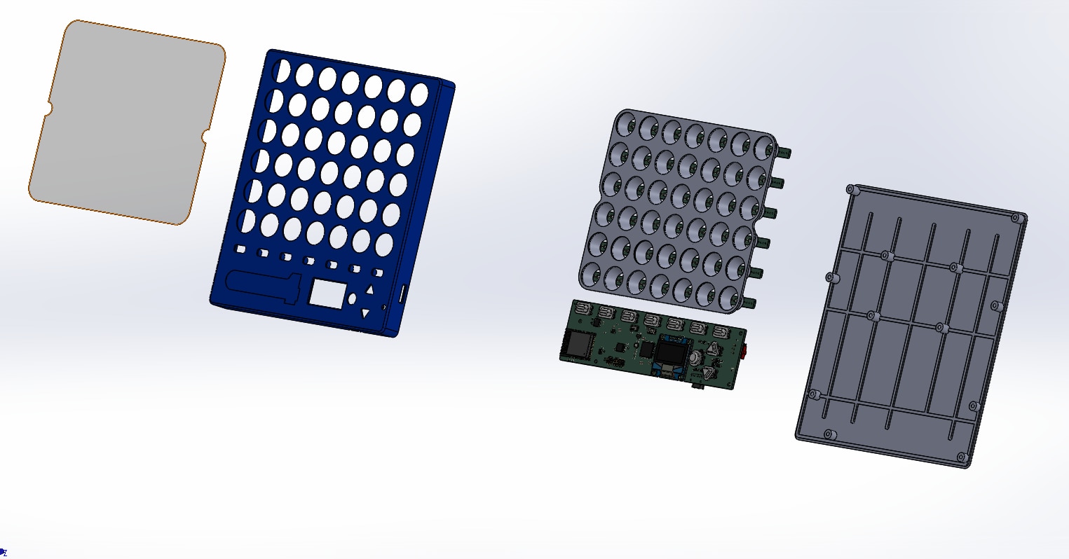
Assembly Pics

Front Casing

Back Casing

Focus Cones
 Screw Inserts for the Cones

Gluing the Cones to the Base

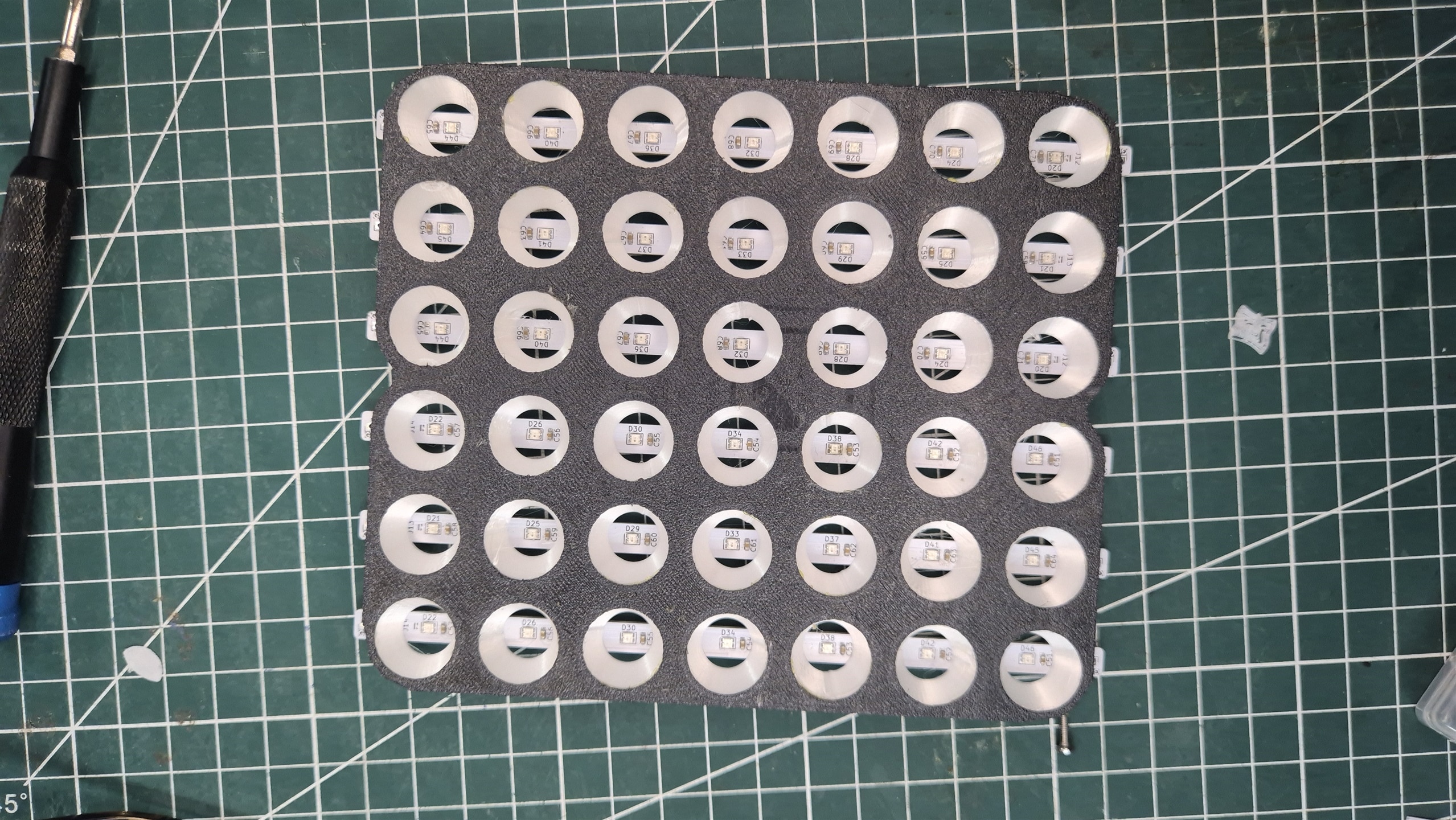
Arranged LED Matrix

Snooping in on the MQTT Messages to make sure everything is Okay.
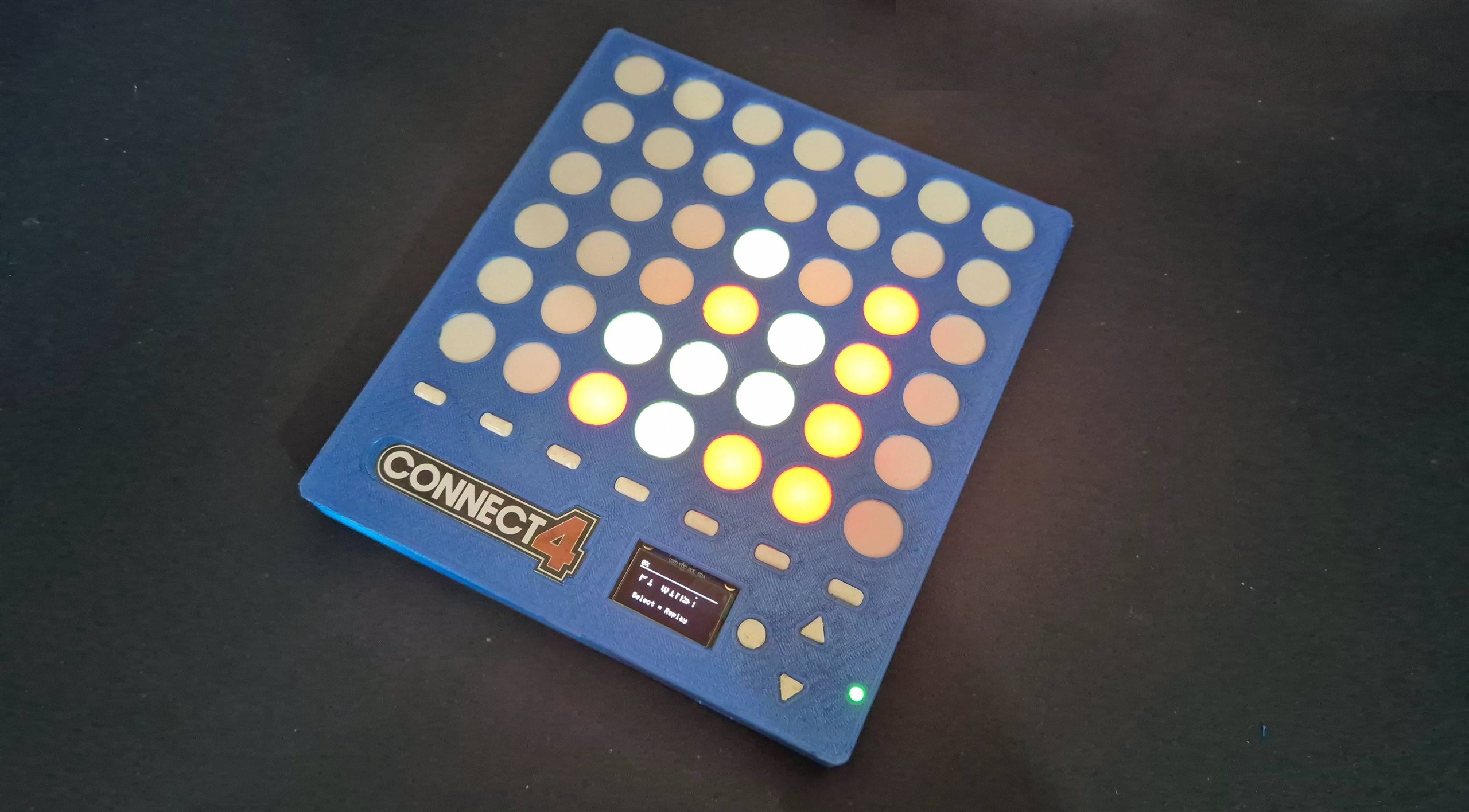
The Final Demo
In the first part of the video, I demo the Hot Seat mode. This is an entirely offline mode of the game, where two players will be using the same device. The device is simply passed from the first player to the second player for the second player’s turn, as the first player makes the first move.
In the second part of the video, I demo online gameplay capability. I Couldnt 3D print the second complete device, so I decided to simulate the second device by using an additional Control PCB,I will be assembling the second complete device shortly, but the current setup already validates the internet-based communication and game synchronization.
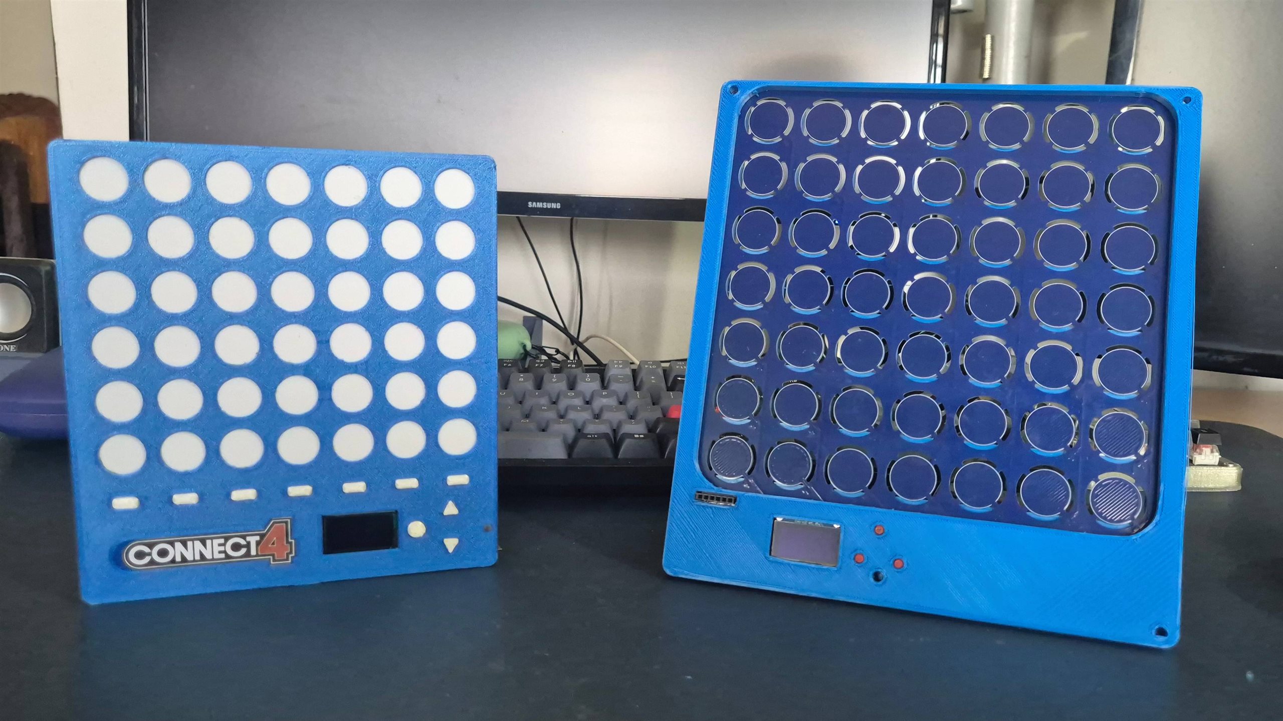
Here is a comparison between V1 and the current version
Some final notes
- I am yet to fix many bugs while playing over ESP-Now
- I need to Reduce the led light creeping on to the next cell.
- I need to make a good video on this
- I started using Typora for my Documentation and it's awesome.
Git Repo
Find the public repo here - https://github.com/arvindsa/connect4 you can find the repo for older versions in my profile too.
Updates done after Submission Deadline:
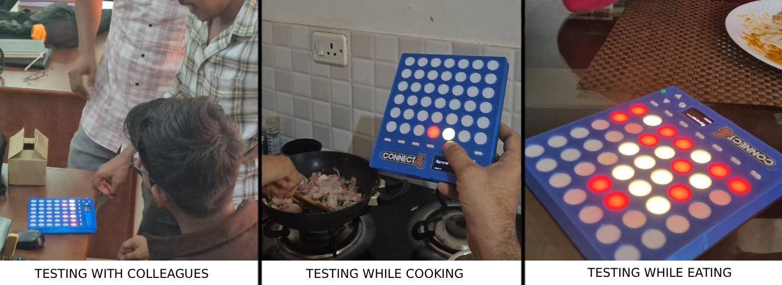
I tested the usability of the device with my colleagues, girlfriend and couple of friends.
Reviews
- Definitely portable and fun to use. They Loved the tactile.
- Size could have been slightly smaller
- Feels solid in hand. (They were referring to the build quality) I added ribs inside the casing to make it more rigid. This was done before the deadline i missed documenting above.
- The Drop effect was realistic.
Things to do
- Fix ESP-Now gaming
- Enable Configuration of Wifi/MQTT to make it actually connect to different wifi. Currently it is hardcoded
- OLED UI Improvement
- Battery life display bug correction
- Name the Players
An Idea from an comment by obones on another project by Gone in 60 seconds! ...more or less. by me_Cris gave me an idea, if at all i am making a next version of this. I'd like to add
- Haptics using DRV2605L
- Use IMU to simulate the drop as well as knocking over the chips

