

Hello makers!
We have here a small demonstration application that is a bit dynamic, it involves some movement, and it is hourglass [[emoticon:c4563cd7d5574777a71c318021cbbcc8]]. I used an MPU6050 circuit that incorporates an accelerometer and a gyroscope, because it is a very easy method by which movement can be detected, and the visual part is represented by 2x LED matrix.
I would like to build something for the desk, to be more visible, and on the list I had an hourglass. The project is at the beginning, you will see why below, but it will be better after I get a helping machine (3D printing combines wonderfully with electronics). Playing around a bit I also got some ideas about what additions I am going to make, so I am not stopping here.
Main components/modules required:
• 1x microcontroller board (Arduino and so on);
• 1x MPU 6050 module;
• 2x 8x8 LED matrices (with MAX7219);
• 1x passive buzzer;
• 1x resistor.
Additional parts such as 5V supply or power jack are also required.
The generic circuit is as follows: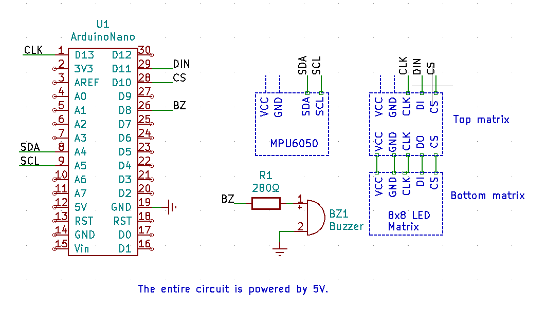
Excuse the unusual appearance, but since we are talking about electronic modules, I think even if they are represented this way it is still understandable.
As a microcontroller, you can use almost anything that is compatible with the Arduino IDE, I have an ATMega328p at hand.
The 2 8x8 LED matrices with MAX7219 driver are connected in cascade.
The module containing the MPU6050 IC is connected to the microcontroller via the I2C interface.
And the passive buzzer has a 280Ω resistor connected to reduce its sound a little (it would actually be very loud without it).
The software is taken from the internet, being open-source, I made small modifications by eliminating unnecessary things for my application. Obviously, it is not perfect, but being a play project, displaying using some animations it is a pretty good start. I will definitely look to make additions. You can find the complete program below.
Hourglass_Project.zip
The functionality of the project can be summarized as follows:
• Situation 1: the hourglass is in a vertical position, or rather the MPU6050 locates the Y axis close to 0°. In this situation, after a short calibration (i.e. a fixed position must be maintained) the flow of 60 dots will start (the matrix has 64), one almost per second. After all the dots have flowed, the hourglass can be turned for a new timing.
• Situation 2: the hourglass is in a vertical position but upside down, i.e. 180° is located on the Y axis. In this case the flow of dots is not possible, the bottom matrix having dots on, must be turned once again to start timing.
• Situation 3: the hourglass is positioned sideways in which case a matrix has dots on and must be positioned vertically to start timing.
Also, in any situation when the hourglass is rotated, you can see how the dots move in the same direction.
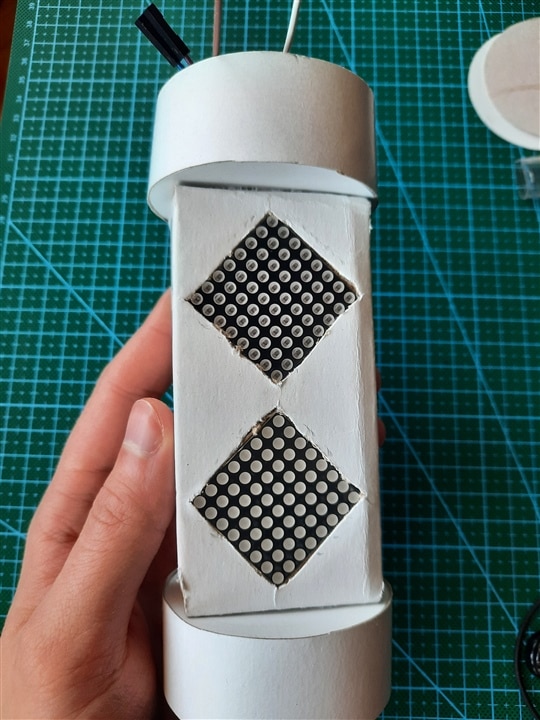
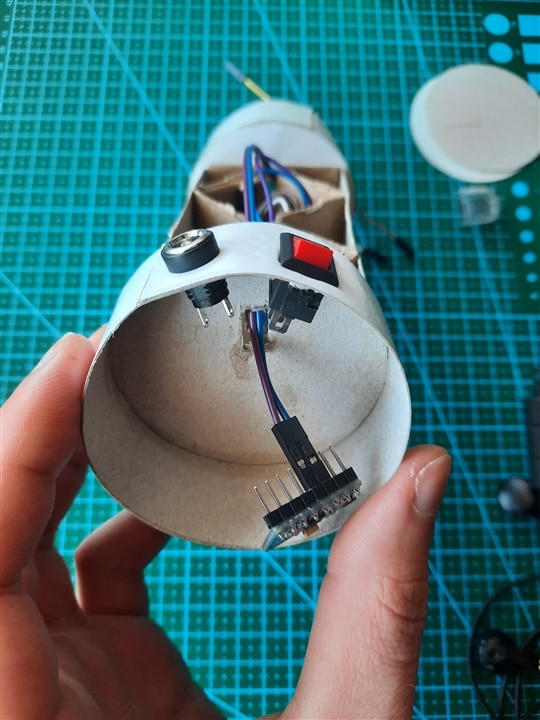
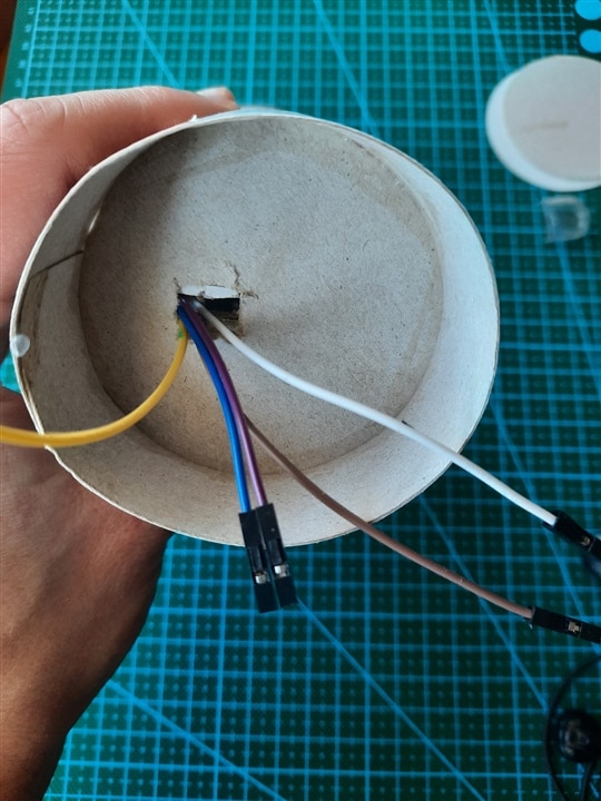
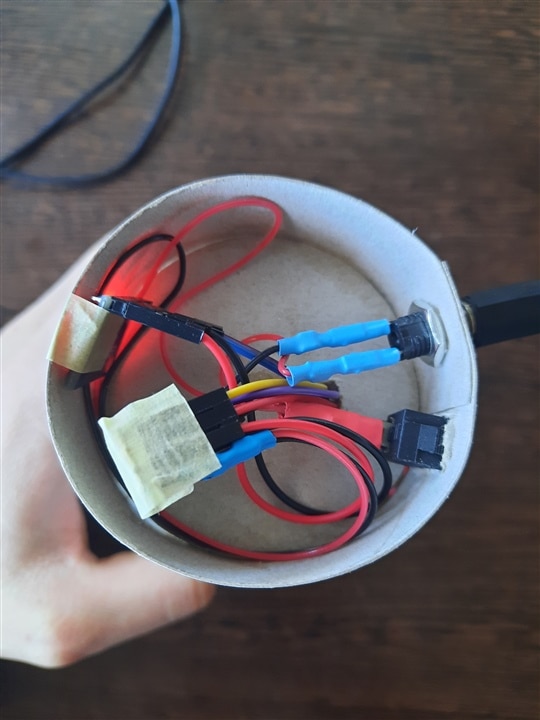
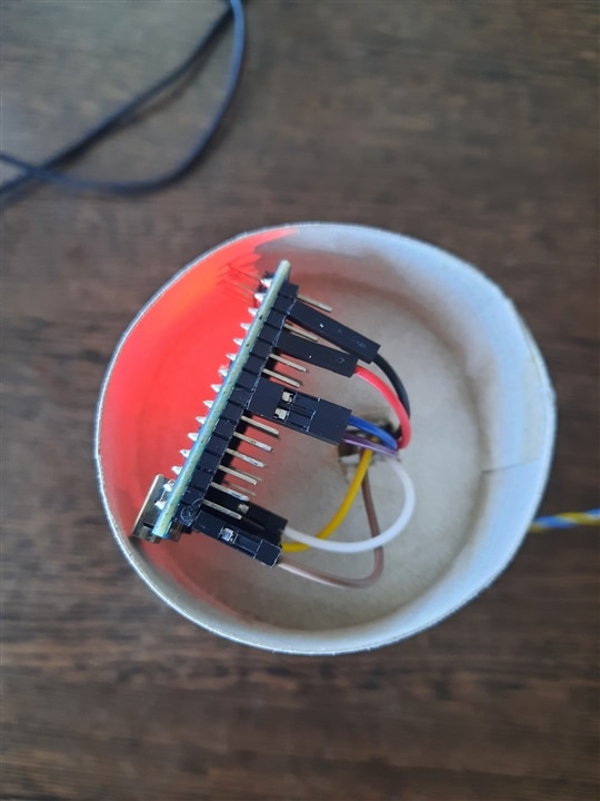
The slightly harder part at the moment is building an enclosure. In the near future I may end up buying a 3D printer which helps a hobbyist a lot, the projects can come out much more attractiv So until then I'm turning again to the most handy material, low cost and unaesthetic, cardboard. [[emoticon:fc35ca29c39f452eb143b6f3a2b4c859]
 ] . Even as unattractive as this looks, I spent a some hours working with scissors and glue to build a body in which to assemble the modules.
| {gallery}Project pictures |
|---|
|
Breadboard tests |
|
Assembly 1 |
|
Assembly 2 |
|
Assembly 3 |
|
Assembly 4 |
|
Assembly 5 |
|
Assembly 6 |
|
Assembly 8 |
|
Assembly 9 |


We also have a demo video:
Enjoy it and maybe it will inspire you to do more! 

