


Retrofit Project:
From Portable Hidden Camera Detector to Illumination Microscope
1 Objective
This project involves the technical upgrade of a portable hidden camera detector, to replace the original red laser LED with white LEDs that are safer for human vision, while maintaining the illumination performance, reengineering overall functionality into the portable microscope observation device.
2 Retrofit Process
2.1 Disassembly and Component Assessment
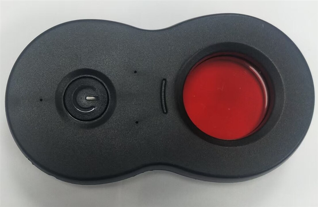
Here is one portable hiddeng camera detector, press the ON button to emit red laser and observe from filter lense for hidden camera.
While the red laser led is harmful to eye and seldom applicable to normal activity.
Retrofit it into something is fun.

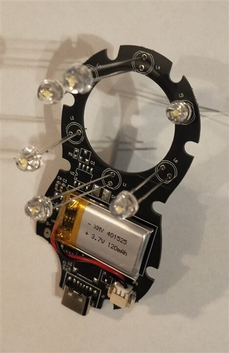
- Carefully disassemble the device casing to access the internal LED array and control circuit.
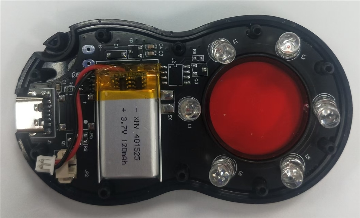
- Remove the laser LED with solder and inspect the original red laser LED configuration: pinout, power requirements, and physical mounting points.
- Inspect the existing PCB traces and power supply to ensure compatibility with the new white LED components
2.2 Component Selection
- Select high-brightness, low-power white LEDs with a color temperature and CRI (Color Rendering Index) suitable for detailed observation.
- Choose components with a similar form factor to the original LEDs to minimize mechanical modifications.
- Verify the forward voltage and current requirements of the new LEDs to ensure they can be safely driven by the existing or modified power supply.
2.3 Circuit Modification
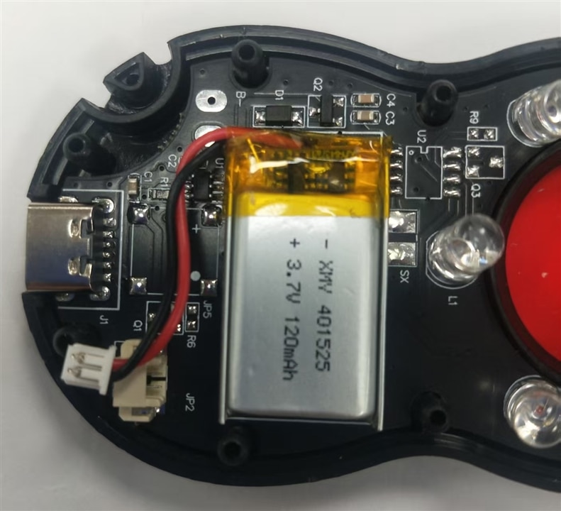
- Remove the original red laser LEDs from the PCB using a soldering iron, check the porlarity and voltage range for safety purpose,
- Check the mechnical form first
- Test whether the porlarity is correct and power on
- Then , solder the new white LEDs onto the PCB, ensuring correct polarity and secure connections.
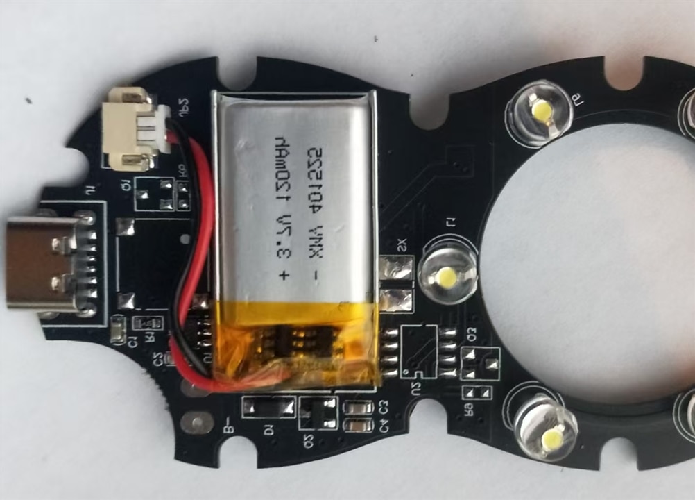
Adjust the raiser length to fit into the case,
- If necessary, adjust the current-limiting resistors on the PCB to match the forward voltage and current of the white LEDs, preventing overheating and ensuring optimal brightness. While, this LED is smaller in size and illumination capability. So, skip it.
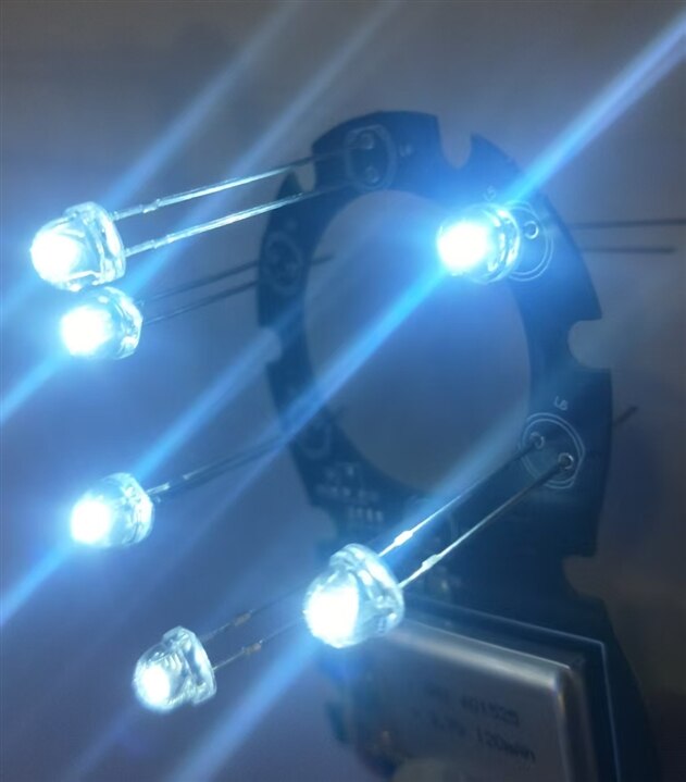
- Test the circuit to confirm the new LEDs light up correctly and the power draw is within safe limits. Bingo, Power on and it work fine
2.4 Mechanical and Optical Part
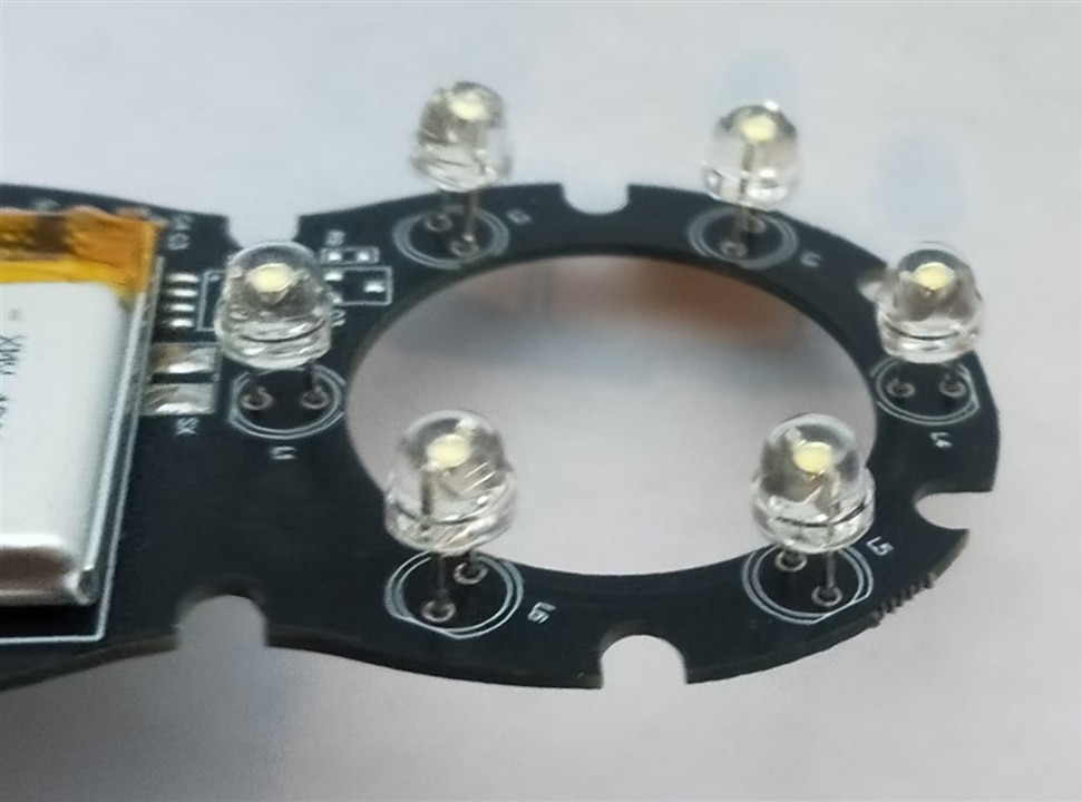
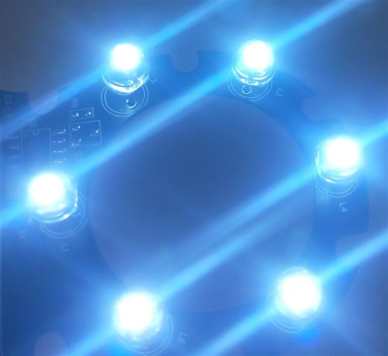
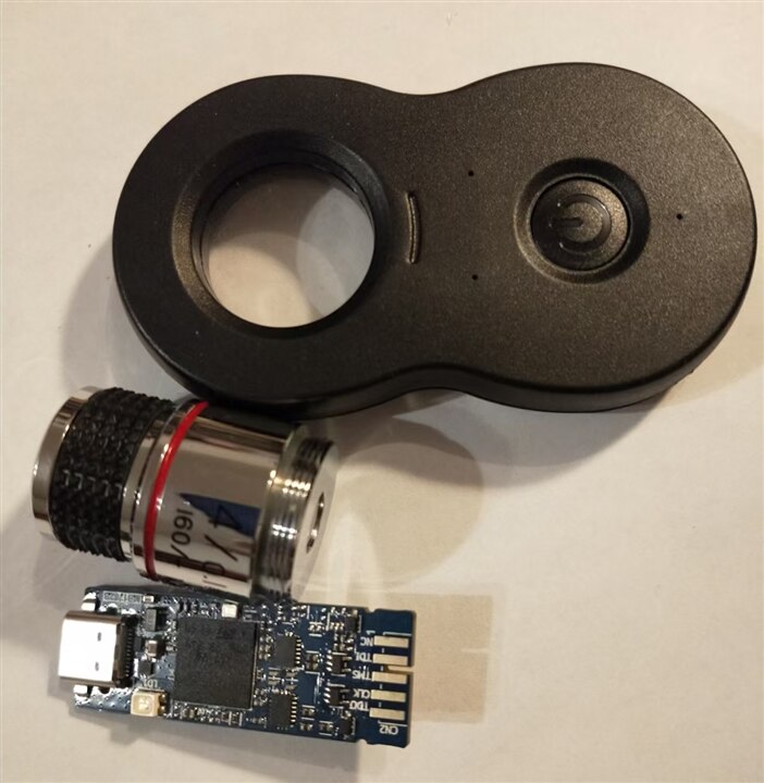
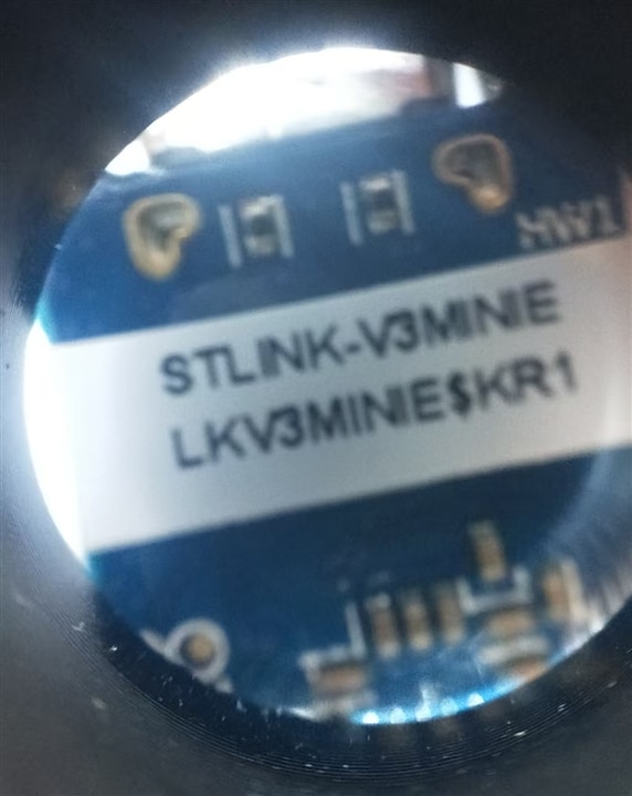
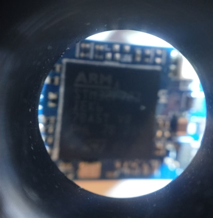
- Ensure the new white LEDs are properly aligned within the circular array to maintain uniform illumination across the observation area.Then colse the case tightly. Off course, I have cut one transparent glass to replace the red one. Then, make the microscope lense ready and one st-link as observation object.
- Check the optical path to ensure the white light is evenly distributed and does not cause glare or hotspots that could interfere with observation.Glue the microscope lense tightly
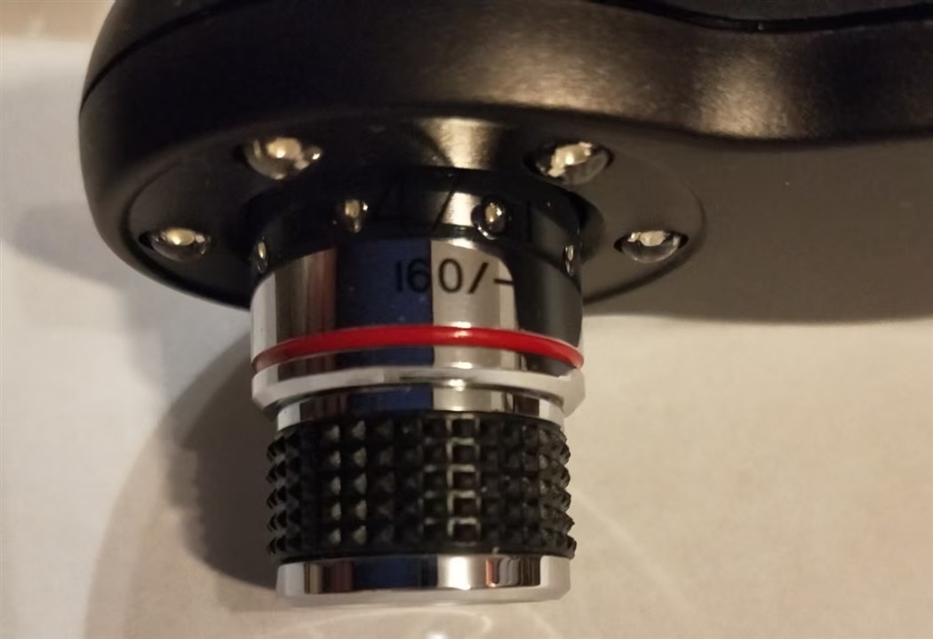
- Adjust the reassembled device casing, ensuring all components fit securely and the LED array is properly positioned relative to the viewing window, align the lense for proper light path
2.5 Testing and Validation
- Power on the device and test the white LED illumination,
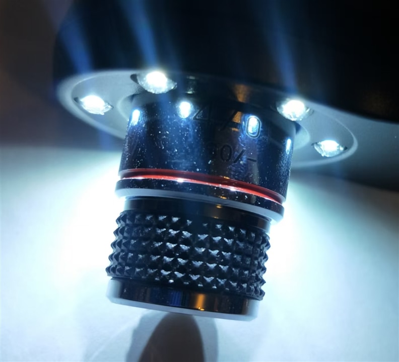
- Verify that the light is safe for prolonged viewing, with no harmful blue light emissions or excessive brightness.Confirm that the observation quality is maintained or improved, with clear and detailed visibility through the lens.
3 Final check
Perform a final check of the device's ergonomics and functionality. It seem well and OK.
4 Bill of Materials (BOM)
4.1 Bill of Materials (BOM)
| Component | Part Number / Spec | Quantity | Purpose | Notes |
|---|---|---|---|---|
| White LED | 5mm, 10,000 mcd, 6000K, CRI ≥ 80, 20mA | 6 pcs | Replace red laser LEDs | Through-hole, clear lens, similar footprint to original |
| Current-limiting resistor | 0805 SMD, 150Ω ±1% | 6 pcs | Match white LED forward voltage (Vf ≈ 3.2V) |
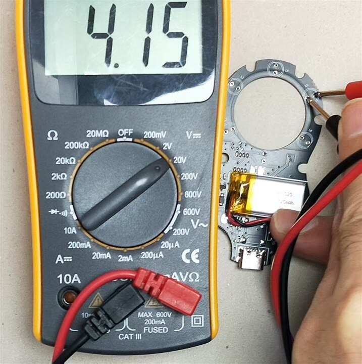
Calculated for 20mA at 6V supply: R=(Vsupply−Vf)/I=(6−3.2)/0.02=140Ω, 150Ω is standard value. For this 4.15V output power, 100Ω is vell off. |
| Solder | Lead-free, SnCuNi | — | ||
| Flux | No-clean, low-residue | — | Improve solder joint quality | |
| Anti-static ESD mat & wrist strap | — | 1 set | Protect sensitive electronics | Mandatory for PCB rework |
| Soldering iron | 30W, fine tip (0.3mm) | 1 | Desolder old components, solder new LEDs | |
| Other |
4.2 Schematic Modification Notes
Original Circuit (Red Laser LED)
- Supply voltage: 4.15V (from internal LiPo battery)
- Red laser LED specs: Vf ≈ 2.2V, I = 20mA
Modified Circuit (White LED)
- White LED specs: Vf ≈ 3.2V, I = 20mA
- LED array configuration: 6 white LEDs in parallel,
Mechanical & Optical Alignment Notes
- LED placement: Ensure the white LEDs are seated flush with the PCB, maintaining the same circular array geometry as the original red laser LEDs.
- Light distribution: Verify the white light is evenly distributed across the viewing window. If hotspots are present, adjust the LED angle or add a diffuser film to the inner surface of the device casing.
- Thermal management: Ensure the PCB has adequate clearance and the device casing has ventilation to prevent overheating during prolonged use.


