


PREAMBLE: For STEM events in the community and schools, I build novel electronic projects, often robotic vehicles of some sort, to engage kids first to have fun playing with them, and along the way inspire their imagination for being creative, start building gadgets and contraptions of their own (secretly awakening the subconscious KNACK & aiming folks down the path of engineering) .
This is one of those unusual projects, built for a robotics program at a for fun nerdy scifi/mystery convention. This convention focuses on fantasy discussion panels, fiction book authoring, film writing and production, and cosplay. The robotics program is a rich complement to the other convention programs as ours includes alot of hands on items.
Our theme this year was Ducks with Hammers, as 10 years ago, our robotics club did a presentation with alot of amazing autonomous robots. For fun, the club founder had thrown together an RC robot in about 10 minutes with spare parts. The robot was radio controlled using two continuous servos and a meat tenderizer mounted on another servo, with a rubber duck glued on top. That robot was by far the favorite of every youngster who attended our program that year. We celebrated that discovery this year by using it as our theme.
THE PROJECT:
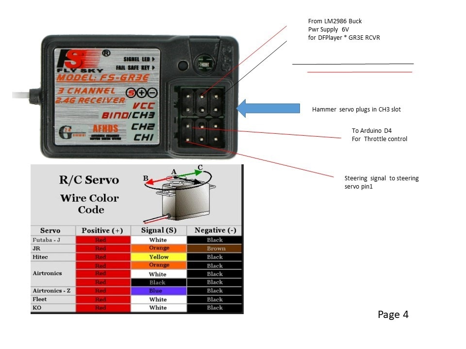
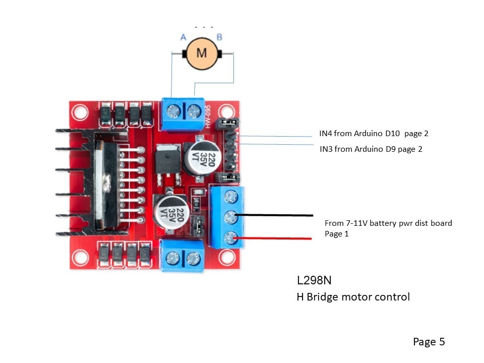
The RC Hammering Duck in the Tub is a radio controlled truck chassis using an Arduino Nano to translate the radio receiver's throttle PWM signal to a 100% duty PWM signal & direction bits to control the H bridge.
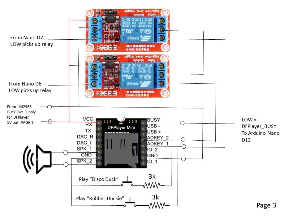
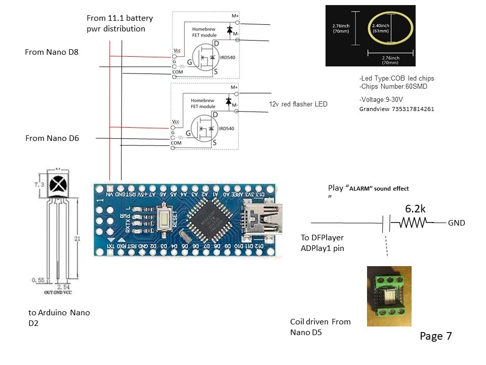
The Arduino Nano also controls a DFPlayer Mini for the sound effects. 2 hidden pushbuttons can play "Rubber Duckie" or "Disco Duck."
When the Duck throttle is engaged, the duck quacks by looping a DFPLayer audio track.
When the hammer swings, a tilt switch wired back to the Nano will fire the HAMMER IMPACT audio file on the DFPlayer.
The Hammer servo is controlled by a third channel on the RC transmitter/receiver.
An IR receiver sits in the bullseye of a duck target. If an IR 38kHz burst is detected, the white LED ring under the duck shuts off, and a flashing red LED turns on. The DFplayer audio sounds an alarm and the H bridge is locked out for 10 seconds.
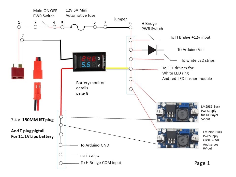
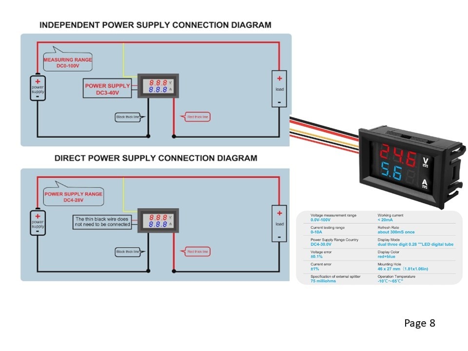
The design includes a main fuse, a main power switch, and a motor power switch so the Duck can be turned on without any chance of the wheels turning. There will be several buck P.S. for 11V to 6V for servos and 11V to 5V for DFplayer.
The OPERATIONAL PROJECT VIDEOS:
https://youtube.com/shorts/bxuNUurVbYg this video was taken at the scifi convention with a youngster playing/controlling the the Duck with Hammer while Im explaining some features. I didnt get a ton of video as we got busy with the crowds in attendance. This video is totally unedited as I have Codec issues between different video platforms.
https://youtu.be/wvT1RfBScMA this short video was taken at the homeschoolers robotics class where I was the special guest speaker demonstrating and explaining the RC Duck with a Hammer as one type of robot project.
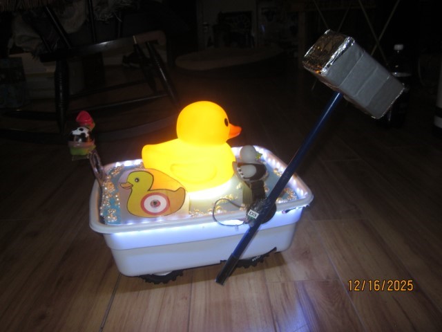
RC Rubber Duck with a Hammer photos:


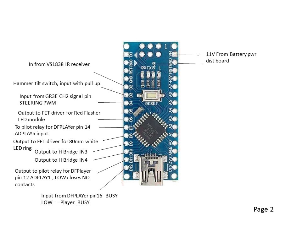
The Rubber Duck With Hammer wiring schematics:

The Arduino Code:
// ---------------------------------------------------------------------------
//RCDuckThrottleControl.ino
// Rememeber to set the IDE Tools/Board = Arduino Nano,
// and set the IDE Tools/Processor = ATMega328P(old bootloader)
//
// This code assumes the RC channels have no mixing, strictly reflecting the position of the joystick.
// if an airplane transmitter - The RC transmitter is selected for MODE 2 , right hand side joystick controls speed (RC receiver Channel 2) and direction (RC recevier channel 1).
// The approach allows the signals to be zeroed and also scaled, since the joystick output doesnt go full scale.
// Use the Arduino serial monitor to get CH1_PWMtime and CH2_PWMtime center and endpoint value to normalize values.
//
// *** MEASURED DATA ****from GR3E receiver and GT3B transmitter
// channel 2 is used for speed reference
// CH2_PWMtime center = 1475 to 1480 usec pulsewidth with trigger at home position  and offset trim at max B30
// CH2_PWMtime full fwd = 2041, usec pulsewidth  ideal should be 2000
// CH2_PWMtime full back = 980, usec pulsewidth  ideal should be 1000
// added an SW offset adjustment
//
// This program and Nano interfaces the L298N H bridge to a FlySky FS=GT3B
//---------------------------------------------------------------------------

int CH2_PWMoffset = 90; //offset counts to CH2 transmitter to zero throttle = 1500 ms
int CH2_PWM_SpdRef_raw = 0; // declare SPD ref raw counts
int CH2_PWM_MAX_counts=200; // max PWM counts for throttle 255 is 100%
int CH2_PWM_MAX_countsFWD=220;
int CH2_PWM_MAX_countsREV=220;

int THROTTLE_RUNNING=LOW;  //initialize
int THROTTLE_RUNNINGlastscan=LOW; //initialize
int DFPlayer_NOT_BUSYlastscan=HIGH; // initialize

int HammerUpTiltSwitch=HIGH; // initialize
int HammerUpTiltSwitchLastScan=HIGH; // initialize

int CannonFireCycle=HIGH;
int CannonCycleCounter=1;
int NoCannonFireLastScan=HIGH;
int NoCannonFire=HIGH;

unsigned long CH2_PWMtime; //pulsewidth time of Channel 2 (into pin 4) RC in microseconds, 1000 = full REV (or -90 degress), 1500=zerospeed or 0 degrees, 2000=full FWD (or +90 degrees)
unsigned long timeout = 23000; //timeout of PWM , set timeout for reading a pulsewidth at 15% moree than max expected 20ms (tried 2300 and caused problems)

int CH2_PWMtime_int; // CH2_PWMtime is an unsigned long, convert it to integer

int LHSFWD=0; // LHS forward bit  driver side the H bridge uses a FWD and REV signal
int LHSREV=0; //LHS reverse bit driver side the H bridge uses a FWD and REV signal

int RHSFWD=0; // RHS forward bit  passenger side  the H bridge uses a FWD and REV signal
int RHSREV=0; //RHS reverse bit   passenger side the H bridge uses a FWD and REV signal

int LHS_PWM_REF_usec ; // magnitude of microseconds pulse width from 1500 usec centerpoint
int RHS_PWM_REF_usec ; // magnitude of microseconds pulse width from 1500 usec centerpoint
int CH2_PWM_REF_usec ; // magnitude of microseconds pulse width from 1500 usec centerpoint
int CH1_PWM_REF_usec ; // magnitude of microseconds pulse width from 1500 usec centerpoint

int LHS_PWM_SpdRef ; // RHS speed reference scaled for 255 = 100%
int RHS_PWM_SpdRef ; // RHS speed reference scaled for 255 = 100%
int CH2_PWM_SpdRef ; // RHS speed reference scaled for 255 = 100%
int CH1_PWM_SpdRef ; // RHS speed reference scaled for 255 = 100%

int LHS_Spd_Ratio=100; // RHS speed reference scaled for 100 = 100%
int RHS_Spd_Ratio=100; // RHS speed reference scaled for 100 = 100%

int Joystick_Right_Pos = 1500; //
int Joystick_Left_Pos = 1500; //


int FWD=LOW; // direction of Channel 2 speed ref
int REV=LOW; // direction of Channel 2 speed ref

int DFPlayer_NOT_BUSY = HIGH;
int DFPlayerToldToRun=LOW;

void setup() {

pinMode(2, INPUT_PULLUP); // from VS1838 IR receiver
pinMode(3, INPUT_PULLUP); // normally open tilt switch, goes LOW when hammer lowered to play hammer sound effect.
pinMode(4, INPUT); // RC receiver Channel 2 motor speed control input

pinMode(5, OUTPUT); // pilot relay to DFPlayer input ADKEY1 with 6.3k resistor. PU relay to PLAY audio track 3
pinMode(6, OUTPUT); // FET driver for red LED module
pinMode(7, OUTPUT); // pilot relay to DFPlayer input ADplay2. LOW picks up relay
pinMode(8, OUTPUT); // FET driver for white ring LED

pinMode(9, OUTPUT); // PWM motor FWD to H Bridge IN3, output forced low in reverse
pinMode(10, OUTPUT);  // PWM motor REV to H Bridge, IN4 output bit forced low in FWD
pinMode(11,OUTPUT); // DFPlayer ADKEY1 LOW SIGNAL PLAYS audio with a one shot
pinMode(12, INPUT); //DFPLAYER BUSY pin LOW is BUSY

digitalWrite(8,HIGH);   // boot up with Rubber Duck light ring on

//Serial.begin(115200);

}

void loop() {


//   Reads a pulse (either HIGH or LOW) on a pin. For example, if value is HIGH, pulseIn() waits for the pin to go HIGH, starts timing, then waits for the pin to go LOW and stops timing. Returns the length of the pulse in microseconds. Gives up and returns 0 if no pulse starts within a specified time out.
// Works on pulses from 10 microseconds to 3 minutes in length.

   CH2_PWMtime = pulseIn(4, HIGH, timeout); // pulseIn(pin, value, timeout)  value is HIGH or LOW, timeout and value are long int
//   Serial.print("CH2 Time: ");
//   Serial.println(CH2_PWMtime);


//  The cast operator translates one variable type into another and forces calculations to be performed in the cast type.
// Syntax (type)variable   Parameters: type: any variable type (e.g. int, float, byte)

     CH2_PWMtime_int = (int) CH2_PWMtime + CH2_PWMoffset; //convert unsigned long to int
 //      Serial.print("CH2 Time: ");
 ////     Serial.println(CH2_PWMtime_int);

     /// create fwd and reverse direction bits

  if ((CH2_PWMtime_int - 1500) >= 50 ){ FWD = HIGH; } else {(FWD=LOW);} // 10 allows some deadband switching bridges
  if ((CH2_PWMtime_int - 1500) <= -50 ){ REV = HIGH; } else {(REV=LOW);} // -10 allows some deadband switching bridges
  if (CH2_PWMtime_int==0) {FWD = LOW; REV =LOW;} // 0 is a missed scan , zero directions

//      Serial.print("FWD = ");
//    Serial.println(FWD);
//     Serial.print("REV= ");
//    Serial.println(REV);

 /// create a speed reference in microsends
 CH2_PWM_REF_usec = abs(CH2_PWMtime_int - 1500); // zero to 500usecs = 0 to 100 % speed
 CH2_PWM_SpdRef_raw = (CH2_PWM_REF_usec/2); // cheap and dirty way to make speed reference, top = 500 microseconds, which corresponds to an analogWrite value 255. divie by 2 makes it just a tad slower.
//     Serial.print("255 is top speed reference, raw count before clamp");
//     Serial.println(CH2_PWM_SpdRef_raw);

///// logic for which speed ref clamp to use
if (FWD==HIGH)
  { CH2_PWM_MAX_counts = CH2_PWM_MAX_countsFWD; }
if (REV==HIGH)
  { CH2_PWM_MAX_counts=CH2_PWM_MAX_countsREV; }

if (CH2_PWM_SpdRef_raw > CH2_PWM_MAX_counts)
    { CH2_PWM_SpdRef = CH2_PWM_MAX_counts; }
    else
     { CH2_PWM_SpdRef = CH2_PWM_SpdRef_raw; }
 //   Serial.print("CH2 max sped PWM reference after MAX clamp");
 //   Serial.println(CH2_PWM_SpdRef);

 // output logic for the H Bridge

      if (FWD==HIGH)
      {
      analogWrite(9, (CH2_PWM_SpdRef));  // analogWrite values from 0 to 255
      analogWrite(10, 0);
       }
    else if (REV==HIGH)
      {
      analogWrite(9, 0) ;  // analogWrite values from 0 to 255
      analogWrite(10,(CH2_PWM_SpdRef));
       }
      else
      {
      analogWrite(9, 0);  // analogWrite values from 0 to 255
      analogWrite(10, 0) ;
       }

/////// END OF THROTTLE SPEED REF PWM CODE

// START OF DFPLAYER CODE --- play audio tracks using inputs ADPLAY1 and ADPLAY5
//DFPlayer play trigger has to be a one shot. BUSY signal takes too long responding to use as a one shot

// AUDIO TRACK SITUATION 1:  if throttle is pressed either direction, start playing Audio track 1 the first time
if ((FWD==HIGH) || (REV==HIGH)) // see if throttle is pressed either direction
    { THROTTLE_RUNNING=HIGH; }
    else
    { THROTTLE_RUNNING=LOW; }

if ((THROTTLE_RUNNING==HIGH) && (THROTTLE_RUNNINGlastscan==LOW))
    { digitalWrite(11,LOW) ; /// LOW causes realy to pick up and clsoe the N.O. contact
    delay (60);
    digitalWrite(11,HIGH);}
    else
    { digitalWrite(11,HIGH); }

THROTTLE_RUNNINGlastscan=THROTTLE_RUNNING;

//
// AUDIO TRACK SITUATION 2:  if throttle is running, and 1st track has played, when DFPLAYER BUSY signal picks back up, play it again
//

DFPlayer_NOT_BUSY=digitalRead(12); // BUSY == LOW when playing

if ((THROTTLE_RUNNING==HIGH)&&(DFPlayer_NOT_BUSY==HIGH)&&(DFPlayer_NOT_BUSYlastscan==LOW)) // means the DFPlayer just finished a track
        { digitalWrite(11,LOW) ; /// LOW causes realy to pick up and clsoe the N.O. contact
    delay (60);
    digitalWrite(11,HIGH);}
    else
    { digitalWrite(11,HIGH); }

DFPlayer_NOT_BUSYlastscan=DFPlayer_NOT_BUSY;

//////////// code to play hammer clang audio track when tilt switch closes and TILT SWITCH input goes LOW /////

  HammerUpTiltSwitch=digitalRead(3); /// hammer Tilt switch LOW = Hammer Down , HIGH=Hammer UP position

  if ((HammerUpTiltSwitch==LOW)&& (HammerUpTiltSwitchLastScan==HIGH))    // edge detect HammerUpTiltSwitch going down
      { digitalWrite(7,LOW) ; /// LOW causes realy to pick up and close the N.O. contact
      delay (60);
      digitalWrite(7,HIGH);}
      else
      { digitalWrite(7,HIGH); }

  HammerUpTiltSwitchLastScan=HammerUpTiltSwitch;

//// END Hammer Audio Play relay //////////////

/////  receiver DISABLE DUCK routine seeing a BurstPulse via the VS1838.
// turn off white LED ring , turn on RED LED module, STOP H Bridge ///


NoCannonFire=digitalRead(2); // VS1838 sensor == HIGH if no 38kHz pulses seen, LOW when a pulse train is seen
//  Serial.print("VS1838 input is high except when a pulse burst is seen");
//  Serial.println(NoCannonFire);

if ((NoCannonFire==LOW)&&(NoCannonFireLastScan==HIGH)) // edge detect falling edge input from high to low to change state
{
    digitalWrite(5,HIGH);  // 1st toggle pilot relay to play sound effect 0003.mp3
    delay(80);
    digitalWrite(5,LOW);
        // disable H bridge - turn on ALERT LED
    digitalWrite(8,LOW); //turn off white LED ring
    digitalWrite(6,HIGH); // turn on red LED flasher
    digitalWrite(9,LOW); //forced H Bridge to zero in FWD
    digitalWrite(10,LOW); //forced H Bridge to zero in REV

    delay(10000);  // 10 seconds disable H bridge
    // return to normal operating conditions
    digitalWrite(8,HIGH); //turn on white LED ring
    digitalWrite(6,LOW); // turn off red LED flasher
  }

NoCannonFireLastScan=NoCannonFire;


}  /// END of LOOP
The Challenges and improvements:
Scope creep and spec changes haunted the RC Hammering Duck.
• Murphy's Law - plenty of spare IOs to start out => digital IO is used up.
• No matter how many power distribution points are provided for power supplies and grounds to eliminate daisy chains, there arent enough. Add more, not enough again. Put some daisy chains in the wire harnesses, still run out. arrgghh
• In spite of strategically placed blocking diodes, when I downloaded new code with main battery power on, opps, the electrons found a sneak path thru the IO and buck power supplies and the Arduino Nano let out a nice cloud of smoke. Luckily only the Arduino suffered as a sacrifice to the project gods.
The Rubber Duck is too heavy. The poor little 7V motor is running at 3A to rotate at 11.3V. The 11.1V Lipo battery full charge volts are about 12.4 , and quickly drops to the nominal 11.1V where the battery delivers the majority of its power.
The batteries have alot of their power left when the voltage drops enough for the motor to stall.
There are about 400mA being drawn by lighting LEDs. The LEDs were added to help the Shark Chase Tank's PixyCam. These LEDs are no longer needed once the PixyCam object detection is upgraded to YOLO.
The driver/operators tend to immediately hit the full throttle when driving the RC Duck with Hammer. There is a slight exponential ramp built into the controller throttle, only active around zero. Adding a rate limit to the throttle PWM Duty cycle will help prevent full voltage slamming the DC motor.
An accel/decel ramp should be even more effective to subdue the motor volts slam, however there is no room on the RC Duck to add a wheel encoder to calculate speed feedback. I'm thinking to also add a current feedback sensor to the Arduino to build a CEMF regulator ( cheap and dirty speed regulator) for the motor. A linear ramp would be applied to the throttle signal as a speed reference, the PID derivative component could be tuned to provide acceleration current.
The RC Rubber Duck with Hammer had a shark chase vehicle. I'll publish that as a second project in this competition.


